Small triode meets innovative FINEMET-core transformer.

Hitachi Metals has taken the lead in manufacturing nanocrystalline iron-based soft magnetic material, which offers high-saturation flux density, high relative permeability, and low-core loss. Hitachi Metals registered its product as FINEMET. Noguchi, a Japanese audio transformer manufacturer, produces a variety of audio transformers especially for tube-amplifier DIYers. It has also offered FINEMET-core audio transformers. I have tried them and the resulting sounds were quite good.
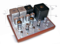
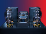
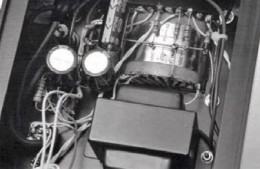
The FINEMET-core audio transformer is renowned among Japanese audiophiles and many audio DIYers want to try it. But the difficulty is the cost. The FINEMET core audio transformers are comparatively expensive. So, many people asked Noguchi to make an affordable one. Recently, the company released its FINEMET core transformer FM-5P, which is a push-pull output transformer that is suitable for a small output amplifier and costs less than $200. I decided to try it in this four-parallel push-pull amplifier project (see Photo 1 and Photo 2).
The amplifier’s primary windings are 10 and 20 kΩ, and the secondary windings are 4, 8, and 16 Ω. The rating is 80 mA through the first winding and 5 W at 70 Hz (see Figure 1). The output transformer is not expensive; however, the total cost was almost $400 because two transformers were needed for this stereo application. That meant I had to find savings when selecting other parts.
Powerful Sound From The 5670W
General Electric (GE) produces the 5670W, which is rated five stars and designed as a voltage-gain tube (see Photo 3). It is the same as Western Electric’s WE396A (2C51). I have often used this tube in my projects and also published some articles on parallel 5670W push-pull amplifiers. The 5670W was designed as a voltage gain tube, but when I use it as output tube, it always sounds powerful. It can rival or surpass general output tubes.
I visited the Classic Components tube shop in Tokyo’s Akihabara district and found 10 of the 5670Ws for $85. This price is very inexpensive, considering the WE407A, which is similar to the WE396A but has a 20-V heater, costs $90 in Tokyo.
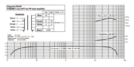
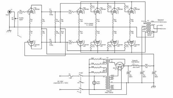
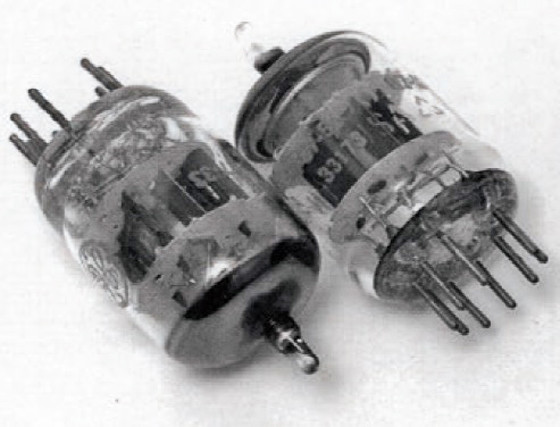
Figure 2 shows the schematic diagram. However, the schematic only shows one channel of the amplifier circuits because both channels have the same configuration. The 5670W plate current is rated around 5 mA for each triode section. As a result, the total amount of plate current would be approximately 80 mA through 16 triode sections of eight 5670Ws. In April 2004, the Japanese audio magazine Radio Technology published my article about a push-pull amplifier based on three parallel WE407As. Its output was a bit more than 2 W, so I estimated this project’s amplifier would have a 3 W output. It is similar to a 2A3 SE amplifier’s output.
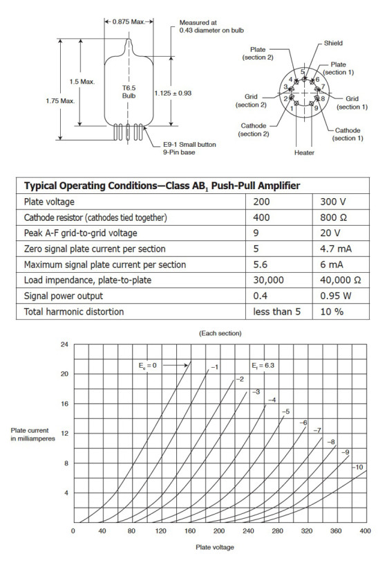
Figure 3 shows the WE396A’s typical push-pull operating condition. When using an 800-Ω cathode resistor for two triode sections and a 40-kΩ resistor as the load, the result is a 0.95-W output.
In this project, I placed four 5670Ws in a parallel and used 10 kΩ as the load. 5670W. The phase splitter is the autobalanced type. A 1.6-kΩ resistor provides cathode bias on the output tube’s cathode. It is unbypassed, as this node is typically used to inject current negative feedback. I didn’t apply the global
negative feedback. The 4.7-kΩ resistor is a grid stopper to prevent spurious oscillation. There is a 1.6-kΩ cathode resistor for each triode section. This technique enables you to check each triode section’s voltage.
As inputs, I used RCA connectors produced by Neutrik. I think the quality of the input connectors is critical to producing good sound. I used the 70-mm × 160-mm × 330-mm chassis because
I needed a 70-mm depth to install output transformers and a power choke.
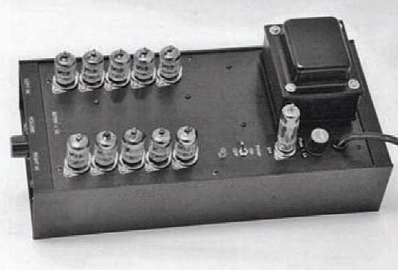
The selected construction is meant to make the amplifier as small as possible. It is fine as a low-output power amplifier. To accomplish this, I didn’t use a lag board terminal around the tubes. Instead, I used 1-mm tin-plated wire to connect the signal to the 5670Ws’ grids. I supported the wire with 4.7-kΩ grid resistors (see Photo 4). In Figure 2, you can see these two wires as two lines located above and below the 5670Ws. I also used the same method to install a grounding wire.
The high voltage is produced from 280-V taps of the power transformer, and it is rectified by a 4 × 6 tube. The Noguchi FMC-3070H power choke is rated at 30 hp and 70 mA. It also features a FINEMET core. Photo 5 shows the power supply’s connections.
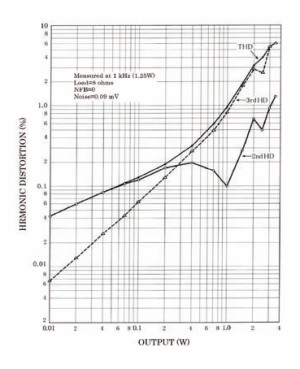
shows a 5.4% THD at 3 W.
The total harmonic distortion (THD) measured 5.4% at 3 W (see Figure 4). The measured noise with no signal input is 0.09 mV. It is low noise due to applying the big power choke (e.g., 30 hp). The ripples of both phases in the high voltage use the push-pull configuration to cancel each other.
The amp manages a respectable –1 dB from 70 to 50 kHz (see Figure 5). It features small output transformers; however, the response result is good.
When I received the 3 W maximum power, the input signal was 1 V (see Figure 6). If you are interested in applying the global negative feedback, you can try it because there is a margin.
Sound Evaluation
To evaluate the sound, I used a three-way speaker system based on the GIP4181 woofer, the WE555 midrange and the GIP597 Type 2 tweeter. The crossover is based on a transformer type attenuator that also features the FINEMET core. Using this, I attenuated the response of the 555 and 597 by –2 dB. I made the crossover point of 4181 and 555 at 500 Hz/–6 dB. I applied a 4-μF capacitor to the 597 as a low-pass filter, which works at 2.5 kHz. I didn’t apply any high-pass filter to the 555.
Starting the listening test, I was impressed with the richness of the low frequency. The sound flowed from the speakers, and I especially enjoyed classic and pop vocals. The sound was excellent and mature. In my opinion, the global negative feedback is unnecessary. Applying it could make the sound too tight. aX

of the amplifier’s wiring.
are shown

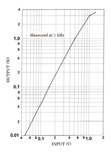
When the amplifier reached the 3-W maximum power,
the input signal was 1 V.
Editor’s note: This article first appeared in the Japanese magazine Radio Technology, December 2011. It was published by audioXpress in March 2013.