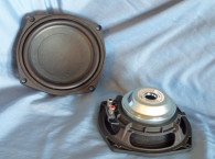
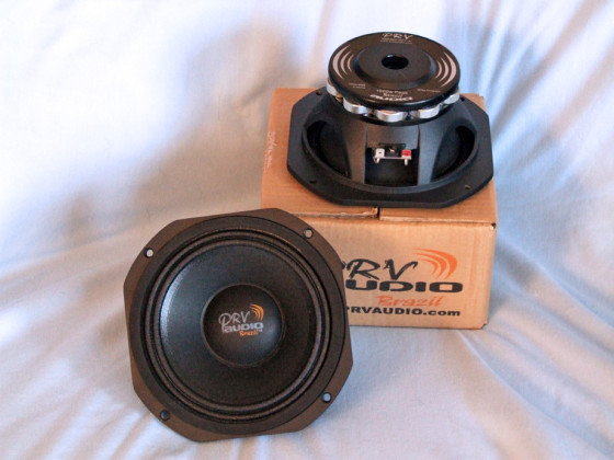
This month’s driver sample comes from Brazilian OEM driver manufacturer PRV Audio Brazil. The 6MR500-NDY-4 is a new 6.5” pro sound midrange from its nine model Midrange Series (see Photo 1).
PRV Audio was founded in January 2006 by former executives and engineers from one of Brazil’s most prestigious loudspeaker manufacturers (I’m guessing it was Selenium) with the goal of producing a comprehensive line of pro audio drivers. PRV Audio opened its factory in southern Brazil and released its first product line that same year. Initially supported by 10 people overseeing design, production, and sales, the original product line consisted of three woofers and two compression drivers.
In 2009, PRV Audio expanded to the US and established a showroom and warehouse in Miami, FL. PRV Audio has continued to expand across the US and established new distributors in Florida, Texas, California, and New York. The product line continues to grow and evolve, as customers take advantage of the sales, service, and inventory of the Miami distribution center. The company exhibited for the first time at the National Association of Music Merchants (NAMM) Show in 2011. During this year, PRV Audio expanded its sales into Mexico, Guatemala, Honduras, Nicaragua, El Salvador, the Caribbean, Venezuela, Colombia, Ecuador, Peru, Chile, East Europe, and South Africa. PRV Audio’s line of loudspeakers, crossovers, array components, and waveguides has grown to include nearly 100 different products in 2014.
Features for the 6MR500-NDY-4 midrange include a lightweight curved profile uncoated treated paper cone, a 2.25” diameter uncoated solid composition paper dust cap and a cast-aluminum frame. Cooling is provided by a 0.87” (22 mm) pole-type vent. Compliance comes from a two-roll pleated coated cloth surround and by a 3.5” diameter elevated cloth spider.
The motor assembly is powered by 10 24-mm × 7-mm neodymium slugs mounted in a circle around the peripheral of the steel front and back plates. Both plates have painted surfaces with the back plate having a 4-mm deep bump out. Driving the cone assembly is a voice coil that consists of a 50 mm (2”) diameter polyimide (Kapton) former wound with copper-coated aluminum wire (CCAW). Voice coil tinsel lead wires terminate to a standard pair of solderable terminals.
I began testing by clamping the 6MR500-NDY-4 to a rigid test fixture in free air. I used a LinearX LMS analyzer and LinearX VIBox to produce voltage and admittance (current) curves at 0.3, 1, 3, 6, and 10 V. I post-processed all 10 10-Hz-to-20-kHz 550-point stepped sine wave curve pairs for each sample and divided the voltage curves by the current curves creating the five impedance curves. I applied the LMS phase calculation procedure to each of the impedance curves and I imported them, along with the voltage curve for each sweep, to the LEAP 5 Enclosure Shop CAD program.
Since most of the Thiele-Small (T-S) data provided by OEM manufacturers is produced employing either a standard T-S model or the original LinearX LEAP 4 TSL model, I used the 1-V free-air curves to also create a LEAP 4 TSL model. I selected the complete curve set, the LTD model’s multiple voltage impedance curves, and the TSL model’s 1-V impedance curves in the transducer derivation menu in LEAP 5 and created the parameters for the computer box simulations.
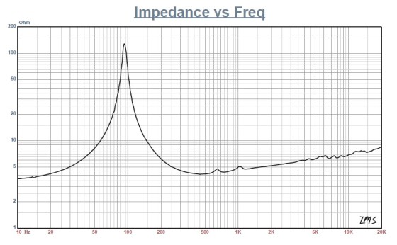
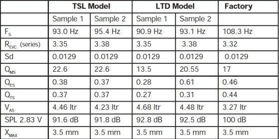
Figure 1 shows the 1-V free-air impedance curve. Table 1 compares the LEAP 5 LTD and TSL data and factory parameters for both 6A samples.
T-S parameter results for the 6MR500-NDY-4 were similar in terms of Fs/Qt ratios, with some variance in the VAS and sound pressure level (SPL). Please note the SPL difference is due in part to two different calculation methods. The LEAP 5 SPL data is a calculated number that is intended to represent midband sensitivity. PRV sensitivities are expressed as the average output across the usable frequency range when applying 2.83 V/1 m, which is perhaps a more accurate presentation of a driver’s overall sensitivity than the calculated sensitivity method. That said, I programmed the computer enclosure simulations using the LEAP LTD parameters for Sample 1. This included a 98-in3 closed box with 50% fiberglass fill material (suggested for midrange applications) and a 87-in3 vented box alignment with 15% fiberglass fill material and tuned to 116 Hz.
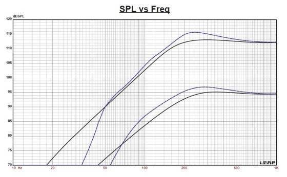


Figure 2 shows the results for the 6MR500-NDY-4 in the sealed and vented boxes at 2.83 V and at a voltage level sufficiently high enough to increase cone excursion to 2.8 mm (XMAX + 15%). This calculation resulted in a F3 frequency of 187 Hz (F6 = 147 Hz) with a Qtc = 0.69 for the sealed enclosure and –3 dB = 149 Hz (F6 = 132 Hz) for the vented box simulation. Increasing the voltage input to both simulations until the maximum linear cone excursion was reached resulted in 113 dB at 25 V for the sealed enclosure and 116 dB for the same 25-V input level for the larger vented box. Figure 3 shows the 6MR500-NDY-4’s 2.83-V
group delay curves. Figure 4 shows the 25-V excursion
curves.
PRV Audio suggests a fourth-order network at 275 Hz for maximum power handling for this driver, so the box simulations are only a guide for designing a passive high-pass filter for the 6MR500-NDY-4. The best format to incorporate this driver into a three-way pro sound speaker with active filters would be to use a fairly large enclosure with a 150-to-200-in3 volume that will give you enough room to apply a reasonable amount of damping material to absorb the rear radiation.
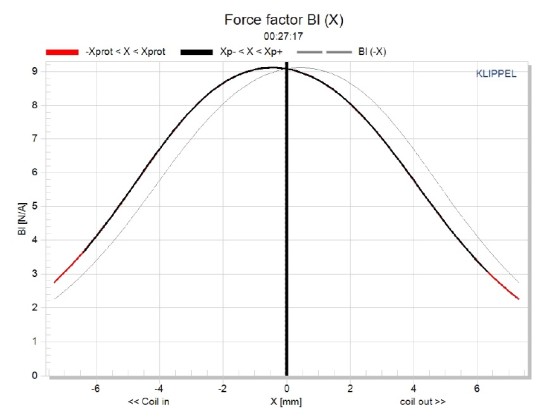
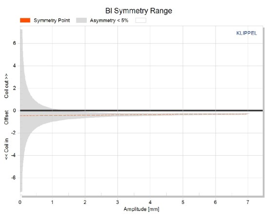
Klippel analysis for the 6MR500-NDY-4 produced the Bl(X), KMS(X), and Bl and KMS symmetry range plots shown in Figures 5–8. Figure 5 shows that the 6MR500-NDY-4’s Bl(X) curve is fairly narrow. But it is expected for a short to moderate XMAX (2.5 mm) pro driver. The 6MR500-NDY-4 is very symmetrical with only a small amount of coil-in offset. The Bl symmetry plot shown in Figure 6 reveals this curve is offset a trivial 0.43-mm coil-in at the rest position gradually decreasing to 0.39 mm offset at the 6MR500-NDY-4’s physical XMAX. Figure 7 shows the 6MR500-NDY-4’s KMS(X) symmetry range curve, which is very symmetrical with a minute amount of coil-in offset. Figure 8 gives the 6MR500-NDY-4’s KMS symmetry range curve, which shows a 0.03-mm coil-in offset at rest decreasing to nearly 0.06-mm offset at the driver’s physical XMAX.
The 6MR500-NDY-4’s displacement limiting numbers (calculated by the Klippel analyzer) were XBl at 82%, Bl = 2.6 mm. For the crossover (XC) at 75%, CMS minimum was 3.6 mm, which means the Bl is the most limiting factor at the prescribed distortion level of 10%.
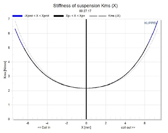
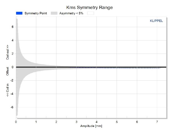
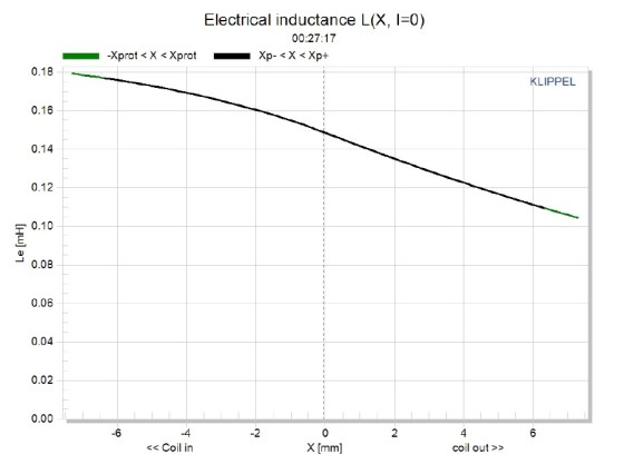
Figure 9 gives the 6MR500-NDY-4’s inductance curves L(X). Inductance will typically increase in the rear direction from the zero rest position as the voice coil covers more pole area. However, from XMAXOUT out to XMAXIN, the inductance range is only 0.163–0.0131 mH. This is only a 0.016-mH delta from the rest position in either direction, which is excellent.
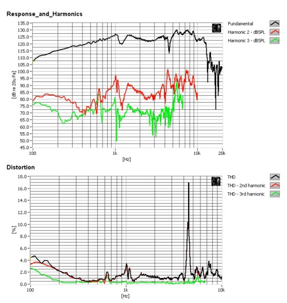
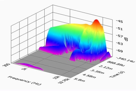
Next, I fired up the Listen SoundCheck analyzer and set it up for distortion measurements. I mounted the 6MR500-NDY-4 in free air and used a noise stimulus set to 104 dB (7.2 V) at 1m with the SPL at 1 m, which is my standard for pro sound products. Figure 10 shows the 6MR500-NDY-4’s distortion curves. Following the distortion measurements, I mounted the 6MR500-NDY-4 in an enclosure with a 12” × 8” baffle and generated an impulse response. This was imported into Listen’s SoundMap software, windowed to remove the room reflections. Figure 11 shows the cumulative spectral decay (CSD) waterfall plot. Figure 12 shows the Wigner-Ville plot.
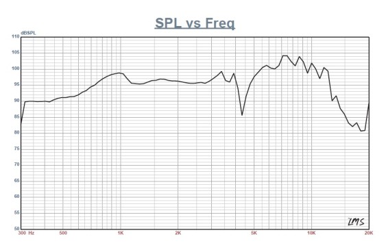
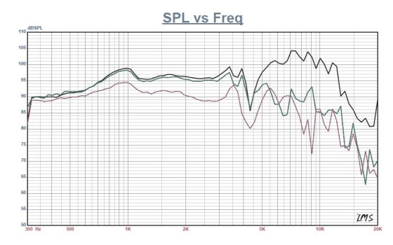
I used the same enclosure as with the impulse response for the remaining series of SPL measurements. Then, I measured the driver frequency response both on- and off-axis from 300 Hz to 20 kHz with a 100- point resolution at 2.83 V/1 m, using a gated sine wave method. Figure 13 shows the 6MR500-NDY-4’s on-axis response, yielding a reasonably smooth rising response out to 3 kHz followed by a twin peak breakup often caused by the surround termination to the cone.
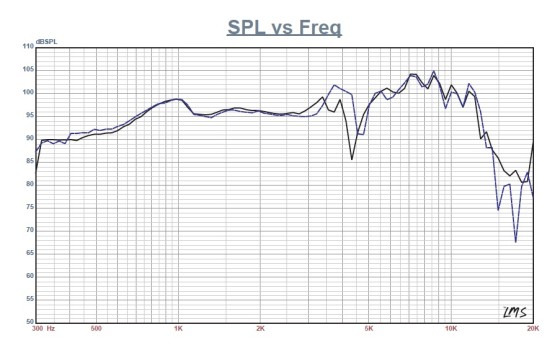
Figure 14 illustrates the off-axis frequency response at 0°, 15°, 30°, and 45°. The –3 dB at 30° result, with respect to the on-axis curve, occurs at 3.7 kHz, which is in the vicinity of the typical 2.5–3 kHz frequently used for 6.5” drivers with 1” domes. Figure 15 shows the 6MR500-NDY-4’s two-sample SPL comparisons, showing both samples very closely matched up to about 3 kHz, which is well within its operating range.
Overall, the 6MR500-NDY-4’s build quality is excellent, as is the objective measurement results, so for its first time in Voice Coil, I’d have to say PRV Audio Brazil is well worth checking out. For more information, visit www.prvaudio.com


This article was originally published in Voice Coil, February 2015.