You can get a good impression of the stability of a power supply under various conditions by loading the output dynamically. This can be implemented using just a handful of components. Apart from obvious factors such as output voltage and current, noise, hum and output resistance, it is also important that a power supply has a good regulation under varying load conditions.
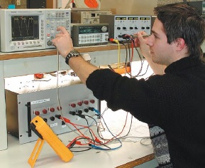
A standard test for this uses a resistor array across the output that can be switched between two values. Manufacturers typically use resistor values that correspond to 10% and 90% of the rated power output of the supply. The switching frequency between the values is normally several tens of hertz (e.g. 40 Hz). The behavior of the output can then be inspected with an oscilloscope, from which you can deduce how stable the power supply is. At the rising edge of the square wave you will usually find an overshoot, which is caused by the way the regulator functions, the inductance of the internal and external wiring and any output filter.
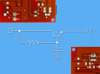
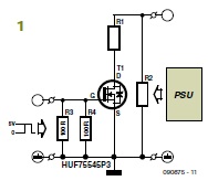
This dynamic behavior is normally tested at a single frequency, but the designers in the Elektor Lab have tested numerous lab supplies over the years and it seemed interesting to check what happens at higher switching frequencies. The only items required for this are an ordinary signal generator with a square wave output and the circuit shown in Figure 1.
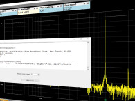
You can then take measurements up to several megahertz, which should give you a really good insight for which applications the power supply is suitable. More often than not you will come across a resonance frequency at which the supply no longer remains stable and it’s interesting to note at which frequency that occurs.
The circuit really is very simple. The power MOSFET used in the circuit is a type that is rated at 80 V/75 A and has an on-resistance of only 10 mΩ (VGS = 10 V). The output of the supply is continuously loaded by R2, which has a value such that 1/10th of the maximum output current flows through it (R2 = Vmax/0.1/max). The value of R1 is chosen such that 8/10th of the maximum current flows through it (R1 = Vmax/0.8/max). Together this makes 0.9/max when the MOSFET conducts. You should round the calculated values to the nearest E12 value and make sure that the resistors are able to dissipate the heat generated (using forced cooling, if required).
At larger output currents the MOSFET should also be provided with a small heatsink. The gate of the FET is connected to ground via two 100-Ω resistors, providing a neat 50-Ω impedance to the output of the signal generator. The output voltage of the signal generator should be set to a level between 5 V and 10 V, and you’re ready to test. Start with a low switching frequency and slowly increase it, whilst keeping an eye on the square wave on the oscilloscope. And then keep increasing the frequency… Who knows what surprises you may come across? Bear in mind though that the editorial team can’t be held responsible for any damage that may occur to the tested power supply. Use this circuit at your own risk! — Harry Baggen and Ton Giesberts (Elektor, February 2010)
Editor's note: This article originally appeared in Elektor, February 2010. audioXpress magazine and AudioXpress.com are Elektor International Media publications.