What stopped me was the lack of a suitable output transformer. That low plate resistance meant that the transformer needed to have low impedance and high current-handling capability. All the available transformers that would handle the current were ridiculously large. Then I ran across Steve Bench’s website (now archived on diyaudioprojects.com.)
Steve discovered that ordinary toroidal power transformers make surprisingly good output transformers. Finally, I had the transformer I had been looking for! What I ended up with is a miniature amplifier with a big sound. It will make a good monitor amp, a great first project, or a suitable introduction to “tube sound.” Power output is a microscopic 3W, but don’t let that fool you. This amp has great bass response, and with efficient speakers, is quite capable of room-filling volume.
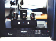
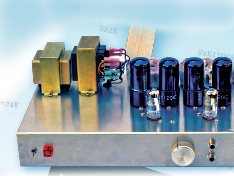
Besides using cheap, off-the-shelf parts, the Mouse is easy to build and modify. It uses a minimum of feedback — 6dB — so it is extremely stable. Frequency response is dead flat from 20 to 30kHz. It even features dual independent power supplies (Photo 1).

The Circuit
The output stage is not unusual, except for the zener diodes, which develop a 15V bias in the cathode circuit. Because the voltage cannot change, it acts like a fixed bias. On the other hand, this voltage develops as a consequence of each tube’s output current, and it comes from the plate supply. These are properties of cathode bias.
The result is thus a combination of the best properties of both types of bias. More important, the diodes will not permit any AC to develop across themselves, so there is no degenerative feedback in the cathode circuit. This contributes to the Mouse’s excellent bass properties.
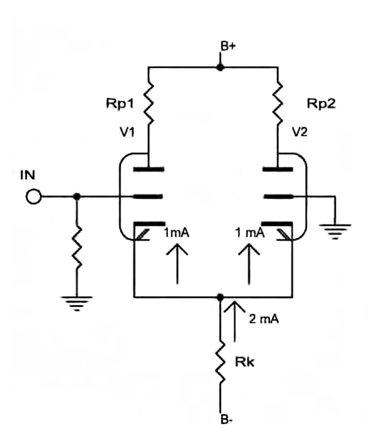
I agonized for some time over the driver circuit. I would have liked to have used an interstage transformer, but cost, size, and performance factors ruled it out. Finally, I settled on the long-tailed pair. Figure 1 is a simplified view of this circuit. Notice that there are two identical branches, and that each branch draws an identical current. This current must be supplied through Rk from the negative supply. In a practical circuit, the internal resistance of each vacuum tube is smaller than its plate resistor, and much smaller than Rk, so the action of either tube has negligible effect on the current flowing through Rk. Yet you know that current must vary through Rp1 in order for an output signal to develop. Where does this current variation come from? The answer is that it comes from V2. Every time the current through V1 increases, the current through V2 must decrease by an identical amount. Because this decreasing current flows through Rp2, an equal but opposite signal develops across Rp2, and you have phase inversion.
How does V2 “know” what V1 is doing? Easy. Suppose a signal were applied to V1 such that its current increased. The voltage across Rk must increase, if only by a tiny amount. This voltage must also be impressed on the cathode of V2. This represents an input signal to V2, and because its grid is grounded, it is the only signal V2 can see. V2 therefore adjusts its conduction accordingly.
Notice that the signal is impressed on V1’s grid, and on V2’s cathode. V1 is acting like a common-cathode circuit, and V2 acts like a common-grid. The gains of these two circuits are different, so the plate resistor of V2 is often made larger to compensate. The whole circuit depends on the degree that the current through Rk can be made constant. Normally, this requires a very large resistor, and a high B- voltage, but you now have the advantage of many new solid-state devices.
One of my favorites is the LM334 current source. This little IC provides an extremely constant current, and it needs only a couple of diode drops to do it! The only extra component required is a resistor to program the magnitude of the current. Figure 2 shows how this IC is employed.
Potentiometer P2 sets the operating current. As long as the bias voltage of V1 is larger than 1.4V, the IC is happy, and as long as the voltage across the IC equals the bias voltage, V1 is happy. I did not use high-voltage protection on the LM334 because it never sees high voltage, even when the tube is cold. If this worries you, bypass the IC with a 12V zener.


Construction
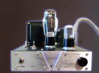
I built the Mouse on an aluminum chassis box, 12 × 8 × 2 (Hammond 1444-22). I found that it was easier to reverse one output tube socket so that both coupling capacitors were on the outside. Other than that, the layout is quite straightforward. Photo 2 shows the overall layout of my amp.
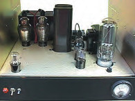
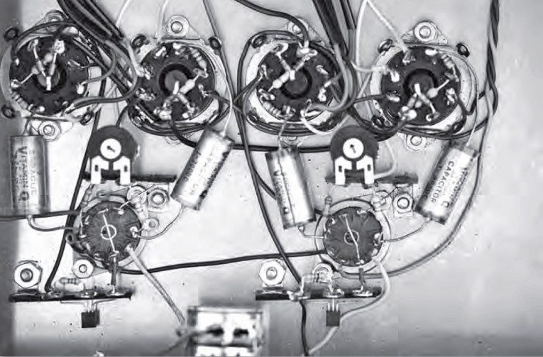
Grounding is relatively uncritical. In the final version, I ran a bus line to pin one of the output tube sockets, then back to the power supply, but in the prototype, I relaxed the rules a little. Both amplifiers are dead quiet, with no trace of hum. You may find it easier to wire up the tube sockets with their associated diodes and resistors before installing them. Photo 3 shows how they are wired. The LM334 gets its own terminal strip; this seemed to be the neatest way to mount it.
You need to allow a couple of extra terminals to mount P2. I did not use a potentiometer in my amp; I tacked a pot in temporarily, then replaced it with the proper size resistor. It takes more steps, but it seemed easier than trying to permanently mount a potentiometer.
Start the chassis wiring with the heater circuit, then the ground wires, signal wires, and finally, the resistors and capacitors. Do not mount the transformers until most of the wiring is done. Once the transformers are mounted, the chassis will not lie flat, and will be much harder to work with. After mounting the transformers, you can do the power wiring.

The power supply is assembled on a piece of perfboard, approximately 2½ × 4¾. If I had it to do over again, I would allow more room for connections to the bridge rectifier. I had originally intended to use wire-wrap pins, which my local electronic store no longer carries. As a result, I had to wire directly to the board. You should be using stranded wire for the input, so you will need to pre-tin the wires before trying to connect the bridge up to them. I mounted the board with 6-32 × ¾ screws and ¼" spacers and nuts. The plate transformer presents something of a problem, because it does not have wire leads.
In the interest of safety, you must use fully insulated quick-connect terminals (Mouser 517-3250)! You will need to place two wires into each of the primary terminals in order to wire the primary in parallel, so be sure to allow for this. You may need to order some of the terminals large enough to accept two wires. Mouser 517-7250 terminals will accept two 18-gauge wires.
When installing the primary terminals, start with one side of the power line, then install the terminals for the other side. Be very careful not to wire the primary out of phase. It takes only a few seconds for the transformer to burn up. (Don’t ask me how I know!)
Remember, it’s terminals 1 and 4, then terminals 2 and 5. There are no such problems on the secondary side. I have added a fuse to the schematic; it’s very cheap insurance, and may well save you the expense and bother of replacing a burned-out plate transformer.
When you’ve finished the assembly, install the 6DJ8 tubes and check that they light normally. Next, measure the 6DJ8 plate voltages and adjust P2 until the voltage is around 75V. This adjustment is not very critical. Finally, install the output tubes one by one, checking that the voltage on pin 8 of each tube is around 15V.
Connect a set of speakers to the unit, and turn it on. If it makes a howling sound, turn it off and reverse either the primary or the secondary leads of the output transformer. Now you are ready to hook up an input and listen to music! aX
This article was originally published in audioXpress, April 2006.
About the Author
Bob McIntyre has retired after spending 40 years as an audio technician. He was reintroduced to tubes in the late 70s while looking for an inexpensive way to build a 50W amplifier; he liked the sound, and has stayed with tubes ever since. Bob’s other hobbies include music, photography, and building computers.
Sources
Antique Electronic Supply
6221 S. Maple Ave.
Tempe, AZ 85283
www.tubesandmore.com
Avel Lindberg Inc.
47 South End Plaza
New Milford, CT 06776
860 355-4711
www.avellindberg.com
Mouser Electronics
958 N. Main
Mansfield, TX 76063
800 346-6873
www.mouser.com