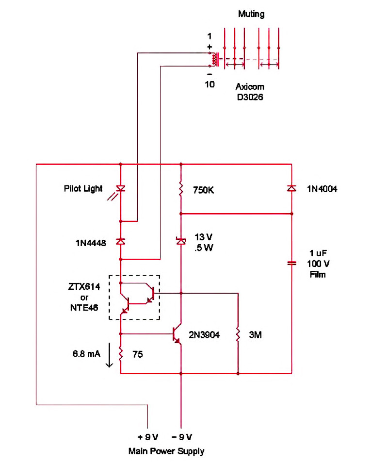
The Circuit
The circuit draws its power from the raw supply rails of the existing preamp, drawing only 7mA of current; you can adjust it for a range of operating voltages by simply changing the value of the zener diode. No connection to the preamp’s GND is needed, so there’s no risk of any annoying ground currents developing. With the values given in the schematic, the turn-on delay is around 1.5 seconds. The turn-off delay depends on the rate of power supply collapse at power-off, because the 1μF timing capacitor discharges through the 1N4004 diode back into the main
supply.
This raises the one word of caution about using such a circuit: The power supply must have sufficiently large power supply capacitors to allow the muting circuit time to switch off before the preamp starts to exhibit anomalous behavior, typically around 50mS minimum. This holds true for any muting circuit to function properly, though.
The ±9V rails represent about the minimum operating voltage for the circuit with the pilot light in series with the relay. If you replace the pilot light with a jumper and change the zener to 10V, the minimum supply rails will be around ±7.5V. The maximum supply rails are around ±45V as you approach the breakdown voltage and power limits of the Darlington. You should select the zener to be around 5 or 6V less than the expected operating voltage, although at higher voltages you can use a greater difference.
The muting relay itself has a DPDT set of contacts (and is available from Mouser Electronics), so you can choose to implement either a series (normally open) or shunt to ground (normally closed) muting scheme (Fig. 2).
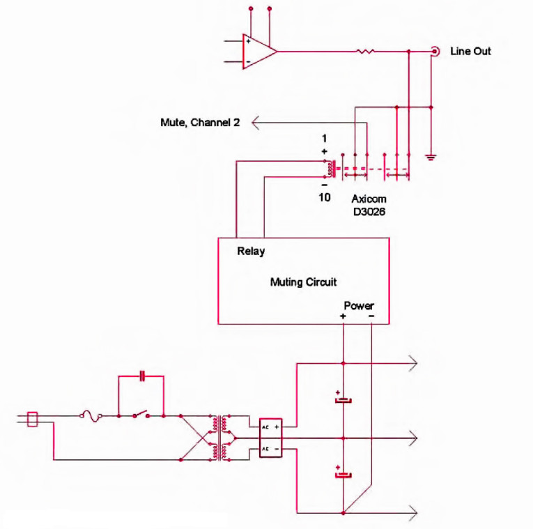
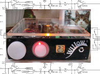
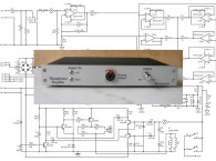
With the exception of mounting the 1N4448 diode close to the relay coil, layout and construction are not critical. In the prototype I mounted the circuit with the pilot light at the front panel and hot-glued the relay to the rear panel using the shunt muting scheme across the RCA jacks. aX
This article was originally published in audioXpress, March 2010