Let’s take a look at the classic loudspeaker: a wooden parallelepiped with two or more drivers mounted on its front panel through screws or bolts, with the driver’s frame rigidly coupled to the panel, or with a foam gasket between the two. In the exact moment that the cone begins to move, it starts to transmit — through the frame and the screws — vibrations to the cabinet and to the other drivers that are fixed on it. These are the contact conduction vibrations.
Moreover, you must consider another sort of transmission of the vibration, the one through the air that is generated by the back of the cone. This kind of conduction is less evident in open baffle systems, because there is no back enclosure, as well as in closed box systems because the large amount of absorbing mats used in this kind of loudspeaker helps to reduce the energy transmitted through the air.
The result of these two types of conduction is that besides the driver, the cabinet also sounds... and it sounds loudly. In fact, in 1975 Barlow(1) measured the sound output of a birch plywood square panel, excited by a driver placed on the inside of the panel, and determined that at the fundamental bending resonance the panel was almost acoustically transparent. In the same year, Stevens(2) presented an even more interesting work: he measured the undamped back panel sound output of a 50 ltr box, made of 18mm chipboard, showing peaks 10dB lower than the driver output. These dB values are worrisome, because they can be easily heard(3). Further and more recent studies by Backman(4) and Moriyasu(5) compared various cabinets of similar volume and panel thickness, but built with different kinds of wood (chipboard, MDF, and plywood), and found minimal resonance differences among the three; nevertheless, it was noticed that MDF and plywood were better at damping the higher modes.
Defining The Problem
To summarize, the driver-induced vibration makes the box sound; therefore, it produces coloration, masking, and detail loss.
Thanks to Iverson(6), you already know that over 1200Hz the panels do not bend very much; therefore, your goal is to raise the panel resonance frequency. To accomplish this, you need to work on material, dimension, thickness, density, rigidity, and damping of the panels to be used. More precisely, with different values for each topic, increasing the thickness and rigidity of a material raises its frequency of resonance. The same happens when you decrease the panel dimension, while increasing the mass and damping will produce a lower resonance frequency.
To build a rigid structure, you can start by using thick panels: for a volume up to 30 ltr, I recommend woods with at least 18mm of thickness; from 30 to 50 ltr 25mm and above 50 ltr it’s wise to go with at least 30mm of thickness. I also suggest some kind of corner joint in the side panels, with the front and back panels inserted in the box, as I did in the Auri loudspeaker (audioXpress 10/06).
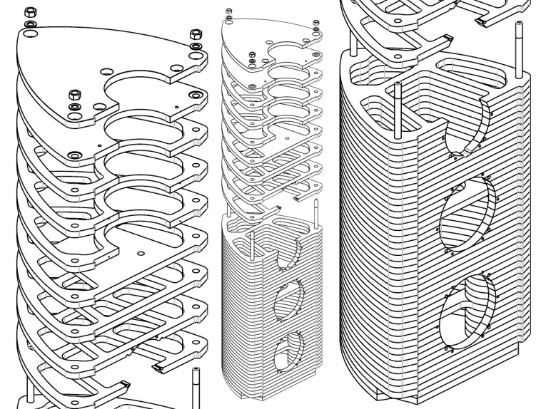
To further increase the box rigidity, instead of employing the classic rectangular form, you can try a curved one, such as B&W 800 or Sonus Faber Guarneri Homage, which, however, doesn’t come cheap. Another recent technique is the translamination (also called layertoning) adopted by Tad and Seventh Veil, in which the box is made by overlapping many wood sheets. As you can imagine, cost and wood waste increases quite a lot. An example of translamination is visible in Photo 1.
Another way to stiffen the structure is to double or triple the number of panels forming the box. Moriyasu(5) reported a reduction of the resonance modes when using a double panel of MDF, in comparison to the single 19mm thick panel, but the increase in weight might be an obstacle, particularly if the speaker dimensions are huge.
The last two cards to play are the bracing (which helps to raise the panel resonance frequency) and the panel damping (which instead lowers the frequency). Bracing is more effective in the vibration suppression, in comparison to damping, but you can use both. But let’s take a closer look at these two techniques.
Bracing
The first step in the war against vibration is the use of reinforcements inside the box, made of high-density hardwood and fixed to the panels with screws and glue. To maximize the contact area between the parts, make a hole in the brace larger than the screw, so the screw threads won’t bite into the brace, while the use of epoxy glue or formaldehyde-based adhesives (not to be used in a too thick layer, otherwise mechanical strength is reduced) adds rigidity.
Vertical bracing is more effective than horizontal, and it is important to place it not in the center of the panel; if the cabinet space allows, you can use more braces set at different distances from each other.
Moreover, you can brace the driver magnet as well, to better distribute the energy involved. Just don’t cover the decompression hole, if present, and don’t interfere with the back cone wave radiation, to reduce the regurgitation effect.
The second step is shelf bracing and involves the use of windowed panels, so that four sides of the box are tied together. The best results are achieved with four holes—rather than a single hole—of oval or circular form, rather than rectangular. It is important that the holes are large enough and the thickness of the shelf not too excessive, so the holes don’t act as reflex ports. You can use more shelves to increase the cabinet rigidity and therefore its resonance frequency. Just remember to place them so they don’t interfere with the driver back emission.
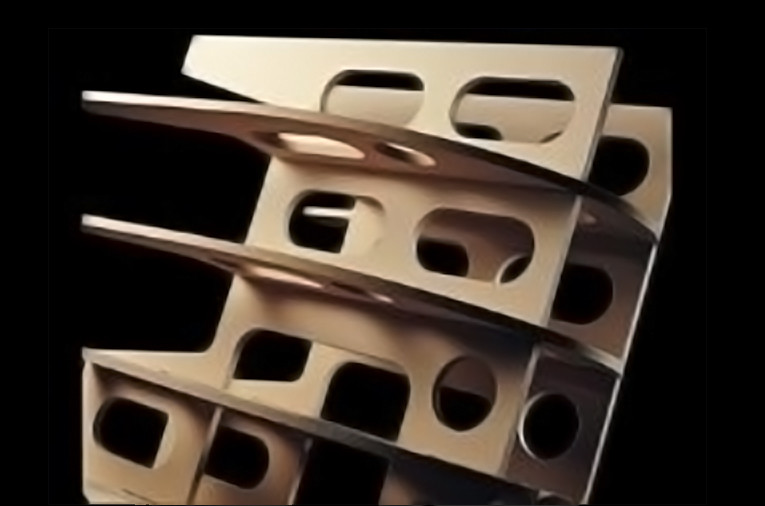
Another step — for sure more complicated — is to build a Matrix-like structure (Photo 2), in which a two-axis grid forms an advanced brace, coupling all the cabinet panels with each other. Those interested in experimenting with such a brace should carefully choose the woofer to be used. Because the Matrix offers to the driver an uneven load (at least more uneven compared to a cabinet without Matrix), a rigid thick damped cone is the better choice. B&W itself adopts drivers with pulp and Kevlar cone, or Rohacell and carbon fiber one, avoiding aluminum cone.
Damping
All materials have the capability of dissipating the energy they receive, properly quantified by the damping loss factor. The higher the value, the better the damping, and a value of 0.6 corresponds to a very good dissipation. Metals usually have a low loss factor, while viscoelastic materials are capable of better damping by transforming the mechanical energy into heat. To raise the damping loss factor of a material, in this case wood, all you need to do is to stick a sheet of damping substance on it, according to one of the following techniques: the extensional damping and the constrained layer damping.
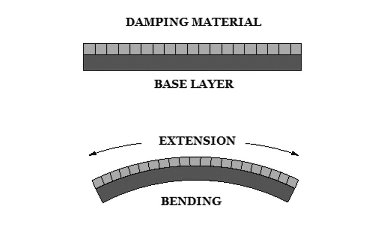
Fig. 1 illustrates the extensional damping (ED): the energy is dissipated by the deformation, due to compression and extension strain, of both layers; increasing the damping layer thickness increases the damping.
The ED is economical and easy to apply, besides offering good results. Some damping material includes lead (which, however, increases speaker weight), the Isodamp C3202-50 by EAR SC, the Fonomat 425 by AZ Audiocomp, the Antiphon LD13, and roofing felt. Be sure to make a strong bond between the damping layer and the base layer to maximize the contact area, as well as to make an age-proof union.
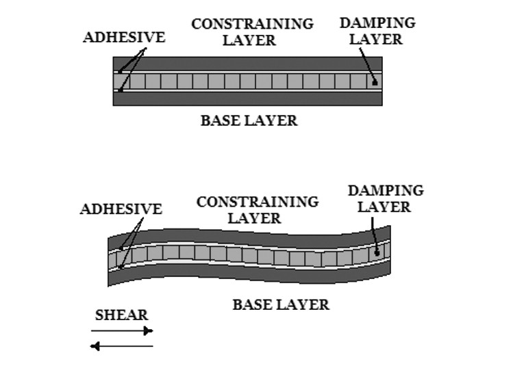
The constrained layer damping (CLD) consists of a three-layer sandwich (Fig. 2), in which the bread slices are the wood layers and the ham is the damping layer. The energy applied to the constraining layer is partially transmitted (shear strain) and partially dissipated (hysteresis) by the damping layer, so the resulting energy that reaches the base layer has been reduced, and its vibrations too. A thicker damping layer doesn’t correspond to a better damping loss factor, as you see in the ED. The best result comes with the layers glued together using a high shear stiffness adhesive.
While more efficient than the extensional damping, the CLD also offers many variants: it’s possible to use different materials and thicknesses for the constraining and base layers, as well as employ different damping layers. The downside is the cost, weight, and time to determine the best variant to use, which implies measurements with an accelerometer. For the damping layer I suggest the Fonomat 225 and the Fonogel by AZ Audiocomp, and the EAR SC CN-12. Plywood is the standard material with CLD.
Contact Vibration Reduction
After this look at how to combat vibration, it’s now time to see what you can do to reduce the energy conduction itself. From Newton’s third law of motion, you know that most of the mechanical energy generated by the driver is transferred to the panel through the frame; therefore, if you decouple it, you reduce the energy that reaches the panel and, consequently, its resonance amplitude. Another positive effect of chassis decoupling is a reduction of driver interaction, because the same energy that reaches the panel goes to the other drivers, too.
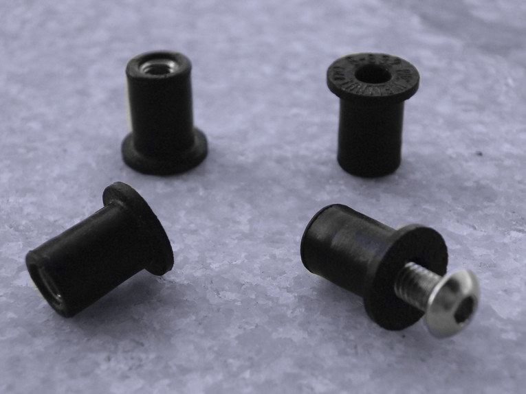
If you use a foam gasket between the driver frame and the panel, you are already applying a decoupling; however, the screws used to fix the driver are another means of vibration transmission. Using some rubber inserts, such as EAR SC Isoloss or Well-nut or Flex-loc, will better isolate the driver. Solving the problem seems an easy task, but it’s not, because the decoupling material has its own transmissibility curve, which says that at certain frequencies the insert and the gasket can act as an amplifier more than a damper.
Look at the past for some examples of driver decoupling: In 1980 Linkwitz used some soft rubber grommets to attach the KEF B110 (Speaker Builder 2, 3, 4/80). B&W, for many years, has decoupled the mid and high cabinets by using Raychem’s Isopath... even if this is useful to diminish the interactions among the drivers more than to reduce the energy that reaches the cabinet panels. KEF, in the golden years of research, used a resilient mounting for the woofer and midrange, to decouple them from the enclosure.
In his article about driver isolation, Moriyasu(5) used a Peerless 831858 woofer with the Well-nuts (Photo 3), and the accelerometer measurement showed a reduction of the secondary modes. In another article about driver isolation, Jones(7) used the EAR SC E-610 to decouple a Pioneer Q13ER71 woofer (only 13cm diameter), and the conclusions affirm that driver diaphragm motion is minimally affected by decoupling the drive unit from the cabinet. In addition, magnet motion and cabinet vibration improve with the decoupled drive, all confirmed by preliminary listening tests.
I decided to conduct my own study on driver interaction, using a plywood baffle (83 × 47cm large and 1.7cm thick) on which were fixed: a 10″ woofer using screws and T-nuts (this will be the exciting driver); a 7″ low-mid driver (Focal 7K4412), the DUT, coupled to the panel with T-nuts or decoupled with Well-nut (1 × 1.3cm M3). Both drivers used a 3mm thick foam gasket between the frame and the wood. To eliminate any crosstalk, I used different generators and amplifiers for each driver.
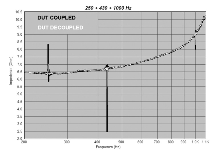
The first measurement was the electric response of the 7" Focal (DUT), while the exciting 10" woofer (EW) played a sine wave signal at 250, 430, and 1000Hz. Figure 3 shows a reduction of the resonance peak when using the DUT and Well-nut (white curve), with respect to the DUT and T-nuts (black curve); the reduction diminishes in amplitude as frequency increases, as you would expect. The measurement was done using the freeware program Speaker Workshop.
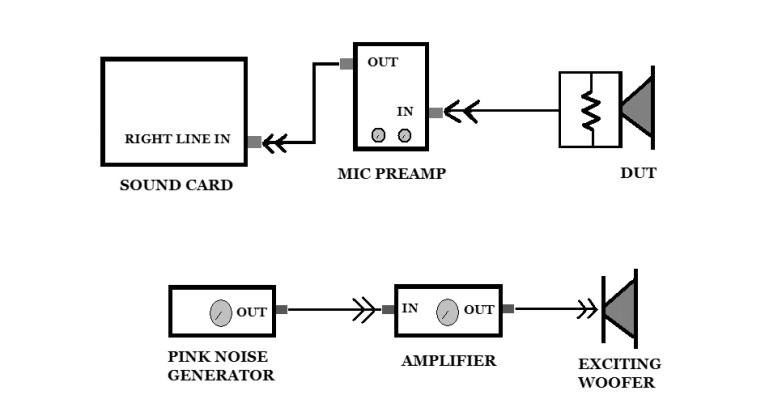
Another kind of measurement arose from a conversation with my friend Valerio Russo, who suggested using the DUT as a microphone. The connections are visible in Fig. 4. The DUT is connected to the mike preamplifier input, while the preamp output goes into the sound card line input; the EW is attached to the amplifier output, whose input is linked to a pink noise generator.
I used a real-time analyzer (TrueRTA), and the amplitude values are not absolute. For this kind of measurement, the Focal mid-woofer was appropriate because it has a rigid cone, a soft suspension, and a wide frequency response. I placed a 0.2Ω resistor in parallel to the driver to simulate the amplifier, as in real life, and therefore used its electric damping.
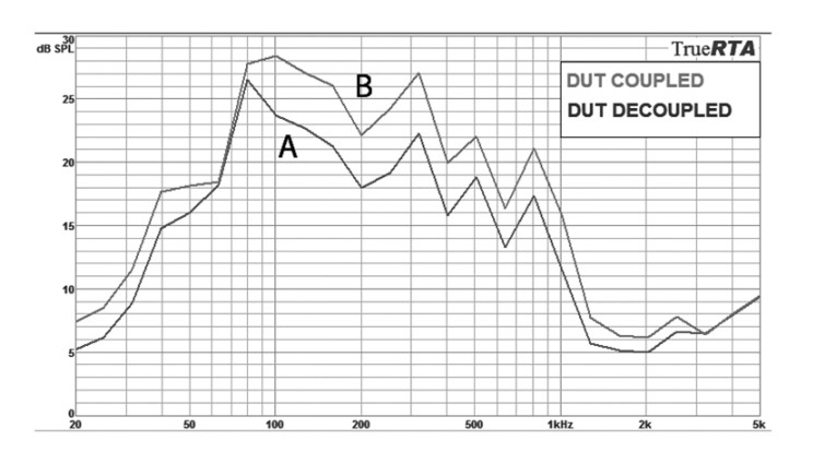
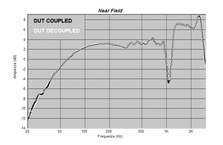
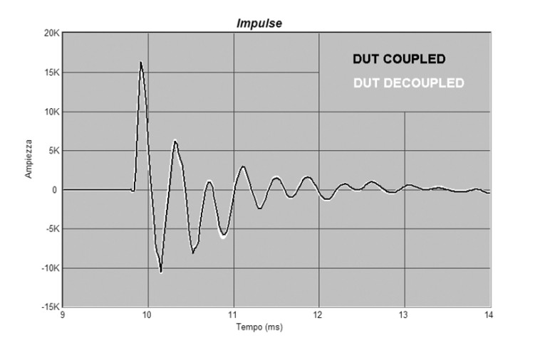
Figure 5 shows how using the Well-nut reduces the energy generated by the exciting woofer in a wide range, with the exception from 65 to 80Hz where the curves are overlapped. So far the Well-nut has helped lower the contact vibrations that reach the driver, but does its use have any collateral effect? To try to answer this question I investigated some more, starting with the impedance response of the DUT and Well-nut and then of the DUT and T-nuts (in both cases I also used a gasket foam). The resonance peak, at the driver Fs, was lower in amplitude when using the Well-nut, bringing a 6% reduction in the driver Qms. I expected this, because the driver-baffle coupling is less rigid employing a damping material.
The next verification was the nearfield acoustic measurement of the two configurations, and Fig. 6 shows the comparison. From 38Hz the curves are identical, with the 1100Hz dip slightly more evident in the rigidly mounted driver; below 38Hz the differences are negligible.
Moving to the far-field measurement, Fig. 7 compares the two impulse responses, in which the DUT and Well-nut have some more evident peaks, but this is nothing to worry about. In fact, both the step response and the frequency response, calculated from the impulse response, have very similar curves.
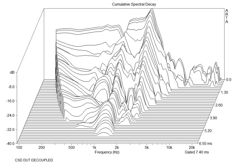
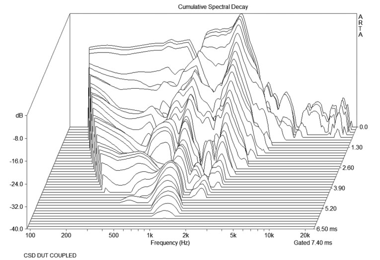
Figures 8-9 show the waterfalls of the cumulative spectral decay, measured with the mike 10cm from the driver dustcap, using the ARTA software. Here, too, it’s hard to notice any difference between the two configurations.
In sum, is driver decoupling the way to go? Unfortunately, there are two answers. Using the Well-nut helps to damp the driver-induced vibrations, but, at the same time, the driver-baffle coupling is less rigid. On one side you gain by reducing the cabinet sound and driver interaction; but on the other side you lose in details and transient response. Each project needs an evaluation of which side is more effective overall, supported by a music listening test.
Conclusion
Driver-induced vibration is a problem with many faces, but there are many ways to reduce its effects, because elimination is quite impossible. A ready-to-use recipe is not readily available, but this article does offer some useful guidelines. My personal recipe for a hypothetical three-way loudspeaker is to use an enclosure for just the woofer, made of plywood with many braces so the panel resonance is well above 1000Hz, assuming the driver will be used until 500Hz.
The midrange is in another enclosure, decoupled from the woofer. This enclosure uses dense wood, such as MDF, and damping mats (lead is a very good choice, because it adds mass); this lowers the cabinet vibrations below 500Hz. And, finally, you can mount the tweeter in the same enclosure as the midrange, but use the Well-nuts to fix it on the panel. aX
References
1. D. A. Barlow, “Sound output of loudspeaker cabinet walls,” 50th AES Convention, Preprint Number: L-17, February 1975.
2. W. R. Stevens, “Sound radiated from loudspeaker cabinets,” 50th AES Convention, Preprint Number: L-16, February 1975.
3. P. A. Fryer, “Intermodulation Distortion Listening Tests,” 50th AES Convention, Preprint Number: L-10, February 1975.
4. Juha Backman, “Effect of Panel Damping on Loudspeaker Enclosure Vibration,” 101st AES Convention, Preprint Number: 4395, October 1996.
5. James Moriyasu “Panel Damping Studies: Reducing Loudspeaker Enclosure Vibrations,” Feb. ’02 audioXpress.
6. James K. Iverson, “The Theory of Loudspeaker Cabinet Resonances,” AES Journal, Volume 21 Number 3, April 1973.
7. A. Jones, “Loudspeaker driver de-coupling, a preliminary report,” Pioneer Electronics Tech.
This article was published in audioXpress, February 2008.