Toaster Test
Pat Brown authored a very interesting and enlightening article (Loudspeaker Toaster, Syn-Aud-Con Newsletter, Vol.34, No.1, Winter 2006) on testing loudspeakers to determine what I refer to as their maximum usable continuous output SPL (SPLMUCO). While a loudspeaker may be capable of producing greater continuous SPL, it is accompanied by significant changes (greater than 3dB) in the transfer function (frequency response) of the loudspeaker. For most applications this is undesirable and thus deemed not usable. This “toaster test” primarily focuses on the thermal effects the input signal has on the loudspeaker system; the individual driver’s voice coils, the resultant impedance increase, and the passive crossover components (if present).
The result of the toaster test yields a maximum RMS voltage (max Vrms) that can be applied to the loudspeaker without driving it past the SPLMUCO. You can then use this max Vrms to calculate an equivalent amplifier size (EAS) which can deliver the max Vrms when driven by this same test signal. This signal, by the way, is specified by the standard IEC 60268. It is a broadband, shaped noise signal with a spectral content that is the average of a variety of program material, including both speech and several different types of music. This test signal has a crest factor of 6dB.
Crest Factor
You need to understand crest factor, so let me briefly explain it. The crest factor of a signal is simply the difference between the RMS level and the peak level of the signal. A square wave has a crest factor of 0dB; it has the same RMS level as its peak level. A sine wave has a crest factor of 3dB; that is, its RMS level is 3dB less than its peak level. For more complex waveforms, the crest factor may be different, and is usually higher.
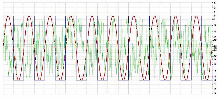
Many waveform editing programs have analysis capabilities that will calculate the RMS and peak levels of an entire .wav file or a selected segment. In Fig. 1 you see 100ms segments of a 100Hz square wave, a 100Hz sine wave, and IEC60268 noise. All of the signals shown have been normalized to have a peak level of 0dB.
Now that you understand crest factor, you can use the results of the toaster test performed on a particular loudspeaker to help determine the required amplifier size for our sound reinforcement system design. Differences between the spectral content of your program material and that of the signal used for the toaster test to determine max Vrms may lead to inaccuracies in my results. However, as long as these spectral differences are not dramatic, the results should be reasonably valid.
Alternatively, you may carry out a toaster test using a test signal having a spectral content more closely resembling the intended program material for the application at hand. For my application the program material to be reproduced by the loudspeaker system will be live speech or music, with little or no compression (amplitude compression, not data compression).
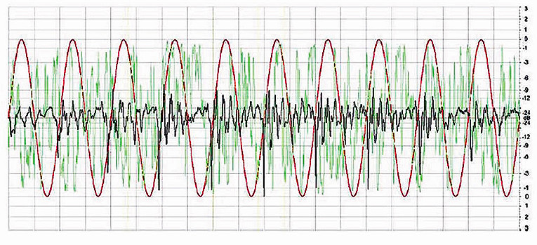
This should give a relatively broadband signal very similar to the IEC 60268 specified noise signal. However, the signal will have a crest factor of approximately 15dB. A time domain comparison of this type of signal to the IEC268 noise and a sine wave is shown in Fig. 2. Here again the peak level of all three signals is 0dB. It should be easy to see that the RMS level of this new speech signal is much less than the noise.
Loudspeaker SPL
The loudspeaker I have selected has a reasonably flat frequency response from 50Hz–12kHz and a sensitivity of 98dB referenced to 2.83V RMS at 1m. At a distance of 10m this loudspeaker will reproduce the IEC268 noise at 78dB SPL when driven with an input of 2.83V RMS. Measure this at 10m to ensure that you are in the far-field for this loudspeaker. It will also reproduce the speech signal at 78dB SPL at 10m when driven with an input of 2.83V RMS.
The reason the measured SPL is the same for both signals is that the RMS input voltage is the same. SPL measured with a slow integration time, which I am referencing here, will correspond well with the RMS value of the input voltage. This is why an RMS meter on a mixing console may be used as a fairly good indicator of SPL once it has been referenced to a particular SPL. Of course, at high input voltage levels the output of the loudspeaker may not remain completely linear and some power compression may occur.
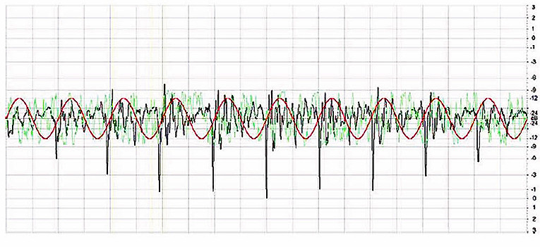
When each of these signals is at the same RMS level, as described previously with the input to the loudspeaker, their peak levels will be different. This is shown in Fig. 3. Here the RMS level of each signal is the same. Now you can see that to cleanly pass the speech signal without clipping I will need a much larger amplifier than required to pass the IEC268 noise cleanly; but exactly how large?
The sound system design requirements dictate that the loudspeaker needs to produce approximately 88dB SPL at 20m with your speech program material. At half this distance, 10m, this equates to 94dB. You know the loudspeaker will produce 78dB at 10m when driven with 2.83V RMS. You need an additional 16dB, or 17.9V RMS, to reach 94dB SPL at 10m.
This loudspeaker has a rated maximum input of 32V RMS as determined by the toaster test. This gives 21dB of gain relative to 2.83V RMS without the thermal limitations of the loudspeaker causing its response to change by more than 3dB. This tells me the loudspeaker can produce the SPL required. In fact, it can be driven 5dB harder. This is good, because thus far I have not accounted for any power compression that may occur.
Because the toaster test limits the response change of the loudspeaker to no more than 3dB, you are assured that this is the maximum SPL reduction that will be encountered. It is much more likely that this 3dB variation will occur not over the entire frequency range of the loudspeaker, but instead over a limited bandwidth. This being the case, the overall SPL reduction will typically be much less. If you know the SPLMUCO of the loudspeaker when driven at max Vrms, then you can calculate the resulting reduction in SPL due to the thermal effects. Including this data on the loudspeaker specification sheet as well as the data files for room modeling programs may be helpful in this regard.
The max Vrms and SPLMUCO ratings for the loudspeaker characterize its performance for one scenario, or type of input signal. You can morph these ratings into other scenarios by changing the crest factor, distance, and desired SPL. This can be done mentally if you are proficient in decibel notation. The following example shows how to calculate this.
Amp Size
To determine the size of the amplifier needed to pass the speech signal without clipping, look at the signal’s crest factor, which is 15dB. You can calculate the peak voltage required from the amplifier using the following equation:
Vpeak = Vrms (CF/20)
For the 15dB crest factor speech signal and required RMS voltage of 17.9V RMS, this gives a peak voltage requirement of 101 Vpeak. A sine wave, with its 3dB crest factor, which has this same peak voltage of 101 Vpeak, will have an RMS voltage of 71.4V RMS. An amplifier rated to deliver 638W into an 8Ω load will meet this requirement.
This is quite a bit larger than the equivalent amplifier size of 256W for this loudspeaker as determined by the toaster method using a 6dB crest factor signal. A somewhat more direct method to determine the required amplifier size is given by the following equation:
RAS = EAS × 10 ((CF-6dB- Gain possible + Gain required)10)
where:
EAS is the equivalent amplifier size given in the CLF file for the loudspeaker.
CF is the crest factor of the anticipated program material. GainPossible is the gain given in the CLF file based on the maximum Vrms. GainRequired is the gain required for the loudspeaker to reach the desired SPL. Subtracting 6dB in the exponent of this equation is necessary because that is the crest factor of the signal used during the toaster test to determine the max Vrms, and subsequently EAS and GainRequired. For our example system design these values would be:
EAS = 256W
CF = 15dB
GainPossible = 21dB
GainRequired = 16dB
So, RAS = 256W × 10 ((15dB-6dB-21dB+16dB)/10)
which reduces to RAS = 256W × 10 (0.4)= 256 at × 2.51 = 643W
There is a slight difference, most probably due to rounding, between this value and the previously calculated 638W. This difference is not significant being less than 0.04dB. A 600 – 700W power amplifier is not exceeding large or difficult to obtain, so it may make for a good design decision to go this route. What if the same loudspeaker was used in an application requiring greater SPL?
Say you needed 91dB SPL at 20m. This is equivalent to 97dB at 10m. This loudspeaker will require 19dB of gain to achieve this. Let me also account for some SPL loss due to power compression by adding another 2dB. This brings you to 21dB of gain required. Coincidentally, this is the limit of the gain possible for this loudspeaker, 21dB. For this higher required SPL you have:
RAS = 256W × 10 ((15dB-6dB-21dB+21dB)/10) = 256W × 10(0.9) = 256W × 7.94 = 2.033W
This is a much larger power amp! But this is required to cleanly pass the 15dB crest factor program material without clipping. When this amplifier is supplying the required RMS voltage to achieve the desired SPL, the voltage peaks delivered to the loudspeaker will be approximately 180 Vpeak! Many loudspeakers can withstand short, transient peaks of very high voltage. This will depend on the frequency content and time duration of the peaks as well as the loudspeaker design. It is always best to check with the manufacturer first or test the peak capabilities of the loudspeaker yourself before deploying such a system.
There are several items that you should keep in mind, in addition to the ones already mentioned, when sizing an amplifier with this method.
1. The spectral content of the program material is very important. If it is not similar to IEC268 noise, you should conduct a toaster test on the loudspeaker in question with 6dB crest factor noise of the appropriate spectrum. The reason for this is two-fold:
A. If there is too much voltage supplied to a loudspeaker driver in the frequency region close to or below its resonance frequency, the excursion of the driver may exceed its safe operating limits. This could result in mechanical damage to the driver. A peak output capabilities test is also very helpful in this regard.
B. If there is not enough voltage supplied to a loudspeaker driver in the frequency region close to its resonance frequency, relative to the overall RMS voltage, there may not be sufficient motion of the voice coil to adequately cool it. This could result in thermal damage to the driver.
2. When using larger amplifiers it is important to not allow them to be overdriven and clip. This can increase the RMS voltage delivered to the loudspeaker and exceed its max Vrms.
3. A decrease in the crest factor of the program material, due to either compression or different program material, may result in a greater RMS voltage delivered to the loudspeaker than its max Vrms. This will occur when the amplifier is driven just to, but not beyond, the point of clipping with a signal having a lower crest factor. This may result in the response of the loudspeaker changing by more than 3dB and also possible damage to the loudspeaker. Care should be taken in the system design to minimize the possibility of this occurring. Both RMS and peak limiters with appropriate time constants may be useful in this respect.
I have examined a method to help determine the required amplifier size so that a given loudspeaker reproducing a given signal may achieve a target SPL at a specified distance and shown an example of how to calculate this. I have also touched on some of the reasons why you must be careful when driving loudspeakers with the very large amplifiers that may result from employing this method. I hope this method will be useful to those designing and deploying sound reinforcement and playback systems.
This article was originally published in Voice Coil, May 2010