It’s convenient to be able to turn your entire system on with one switch. But, power amplifiers are high-current devices and should never be plugged into a switched power outlet on the back of a preamp. Plug them into their own line conditioners, AC regenerators, or directly into an AC wall outlet.
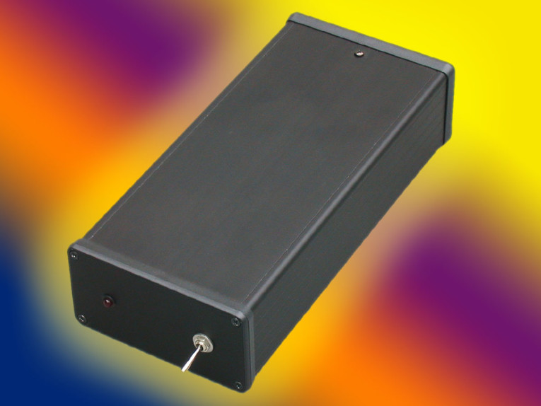
I use three PS Audio Power Plant Premier AC regenerators, one for my low-level equipment and one for each mono power amp, each fed by a dedicated AC line.[1] With the trigger supply, my entire system can be turned on and off with one low-current switch (see Photo 1).
Supply Circuit
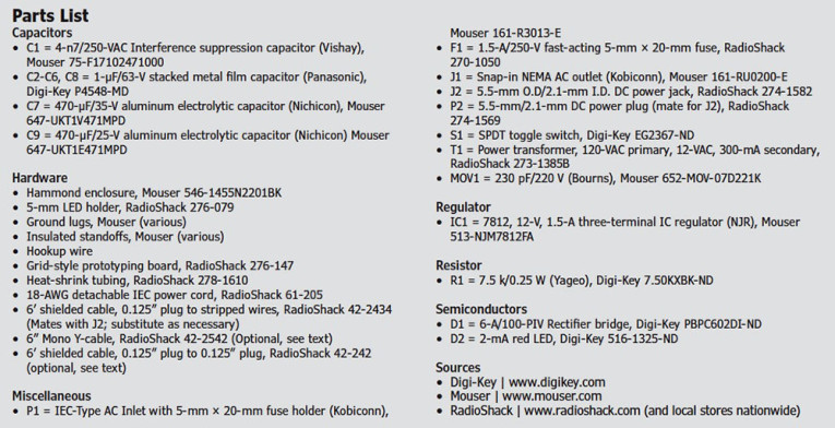
Figure 1 shows a simple 12-V trigger supply that uses a Kobiconn AC Inlet with an International Electrotechnical Commission (IEC) AC connector and a built-in 5-mm × 20-mm fuse holder. I included a Kobiconn AC outlet right after the power switch to trigger older line conditioning equipment (e.g., the Adcom ACE-515), which requires a 120-VAC trigger voltage. This AC outlet is only intended for low-current triggering applications. Don’t attempt to power any audio equipment directly with this outlet. I included an MOV for modest protection against power surges and lightning.

The power transformer can be purchased at any electronics parts store. It also has a 12-VAC/300-mA secondary. I used a full-wave bridge rectifier—6 A is obviously overkill, but it’s the lowest current rating you can normally find on an encapsulated bridge. The three-terminal IC regulator is a 7812 type with a TO-220 case. Many semiconductor manufacturers make these—the brand isn’t critical and a heatsink is not necessary. The input and output electrolytics are bypassed with 1-F film caps. Use a 35-V electrolytic on the input side, and 25 V on the output.
Some builders may consider the film bypasses overkill in a supply strictly intended for trigger application, but this a sensible practice in any power supply and the cost is minimal. The same is true of the four snubber caps across the rectifier diodes. The 2-mA LED and series resistor form the pilot lamp. The output connector, J2, is a standard DC power connector. Normally these have three terminals: chassis, sleeve (supply negative), and tip (supply positive). I recommend not connecting supply ground to the chassis connector — use the sleeve connection only.
Hammond Enclosure
For decades, audio builders and amateur radio operators have relied on Hammond Manufacturing as a prime source for high-quality enclosures and transformers. For this project, the Hammond 1455-series enclosures seemed a natural choice. These nicely finished, extruded aluminum enclosures are available in a clear- or black-anodized finish, with either aluminum or plastic end pieces.
The enclosures have U-shaped bodies and slide-in bellies that can function as the top or the bottom plate, depending on your personal preference and project layout. The enclosures are supplied with a pair of black ABS plastic bezels for mounting the end pieces, but their use is optional.
Hammond includes all the hardware and four adhesive rubber feet. It sells replacement end pieces separately, which is nice if you make a mistake or have second thoughts on the layout. The 1455N2201BK model — with a black anodized finish measuring 8.66” x 4.06” x 2.09”—is just right for this project.
PS Audio specifies a range of 5 to 15 VDC for its AC regenerators and line conditioners. The voltage requirements may vary with products from other manufacturers. Although 12 V is fine for most products activated with a DC trigger, you can easily adjust the output voltage by substituting a different 78xx-series regulator and power transformer. The transformer secondary AC RMS voltage should be the same as the regulated DC output.
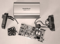
The PS Audio Power Plant products and the Quintet line conditioner have 3.5 mm (0.125”) miniphone trigger input jacks. You will need a cable to get from the trigger supply’s output to the triggered device’s input. RadioShack sells a 6’ patch cord with a 0.125” plug on one end and stripped wires on the other. These ends can be soldered to P2, the DC power plug (P2 is not shown in the schematic).
Although each PS Audio power product has a pair of jacks, they are not feed-through — both are trigger inputs. If you want to daisy-chain more than one unit, you’ll need the 6” Y-adapter and 0.125” cables. Since the trigger inputs on these products draw a minuscule amount of current, several can be daisy-chained together. Most Parasound products use 2.5-mm sub-mini jacks. There’s an input jack and a feed-through loop for daisy-chaining several Parasound products, so there’s no need for a Y-adapter. Use a cable with a 2.5-mm (0.094”) plug for the Parasound products.

Construction
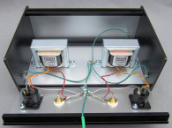
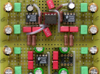
I used the Hammond enclosure’s underside as the bottom plate (see Photo 2a). The power transformer, the rectifier bridge, the capacitors and the three-terminal IC regulator are mounted on a small grid-style prototyping board. Don’t rely on the transformer’s solder terminals to hold the transformer in place. Use a pair of 4-40 machine screws to secure the transformer to the board.
Use insulated standoffs to mount the board to the bottom plate. Mount the IEC-type AC power inlet, AC outlet, and DC p ower jack on the r ear p anel (see Photo 2b). Mouser’s website (www.mouser.com) has datasheets for the Kobiconn power receptacles available as downloadable PDF files. The datasheets include panel cutout dimensions. MOV1 can be soldered directly to the AC outlet’s terminals using insulated sleeving on the leads. Mount the main power switch S1 and the pilot LED on the front panel with capacitor C1 soldered directly to S1’s terminals. I recommend using heat-shrink tubing on all soldered terminals where 120-VAC line voltage is present.
One of the problems with modular, anodized enclosures (from any manufacturer) is that the anodized finish is an insulator, making electrical connection of the various chassis pieces a hit-or miss proposition. I always ensure all the pieces have chassis ground potential by installing a chassis ground lug on each piece and connecting them with soldered ground wires.
The ground lugs can share mounting holes with one of the AC Inlet mounting screws on the rear panel, one of the prototyping board mounting screws on the chassis’s underside, and the AC power switch. (You’ll need one with a 0.25” mounting hole for the power switch. Mouser has a large assortment of ground lugs.)
Grind away the anodizing to ensure a good connection to the chassis. A Dremel-style hobby tool (mine is actually a Sears Craftsman) with a small grinding wheel works well. The U-shaped body can also be fitted with a ground lug which, when used with a push-on connector, facilitates ground connection with the rest of the enclosure, and enables easy removal, if necessary (see Photo 3). After assembling the supply, stick the supplied adhesive rubber feet to the bottom of the enclosure.

Testing
Once the supply is finished, it is ready for testing. Before connecting the AC to the unit, ensure the wide contacts on the AC inlet and outlet are connected to neutral and the narrow contacts are hot (see Figure 1).
Turn the main power switch off and install a 1.5-A, fast-blow, 20-mm fuse in the Kobiconn AC inlet. Then, connect an IEC power cord to the AC inlet and insert a standard AC outlet tester (available at any hardware store) into the AC outlet. Plug the other end of the power cord into a live AC outlet and use the main power switch to turn the unit on. Check the outlet tester’s lights to ensure the AC outlet is properly wired. Then, use a digital multimeter (DMM) to check the DC voltage at the IC regulator’s output and the DC power connector’s center pin. It should read 12 V in each location. The front panel LED should also be illuminated.
If the unit passes all the tests, turn it off, disconnect the power cord, and assemble the enclosure. Slide the enclosure into the slots on the U-shaped body. Slip the plastic bezels over the end pieces and onto the enclosure’s ends. Use the supplied screws to fasten the end pieces and bezels to the chassis. The trigger supply is ready to use. The Hammond 1455-series enclosure looks professional and should make an attractive companion to the rest of your audio components. aX
Reference
[1] G. Galo, “Keep It Clean,” MultiMedia Manufacturer, July–August 2010, and audioXpress, January 2011.
Sources
ACE-515 Line conditioner
Adcom | www.adcom-usa.com
1455-Series enclosure
Hammond Manufacturing Co., Inc. | www.hammondmfg.com
Power Plant AC regenerators
PS Audio | www.psaudio.com
This article was originally published in audioXpress, November 2013.