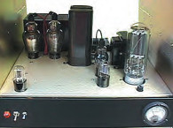
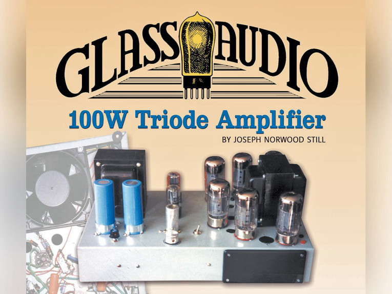
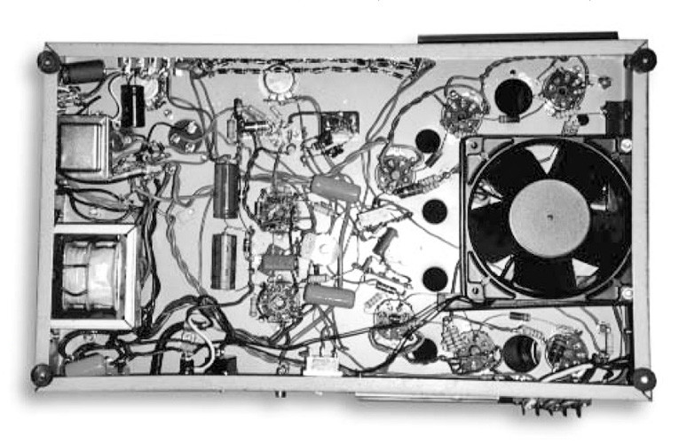
My othery published articles (“40 Watt Triode and 60 Watt Ultra-Linear Amplifier,” GA 2/98, and “70 Watt Low-Distortion Triode Amplifier,” GA 5/98) established the limits for maximum power output for 6550s operated as triodes. My latest amplifier (Photo 1) establishes a new limit by using Hammond transformers and the very rugged Svetlana 6550s.
Design Features
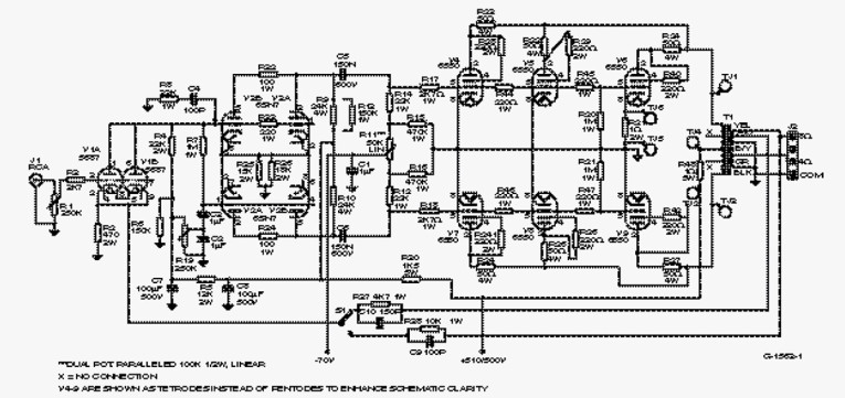
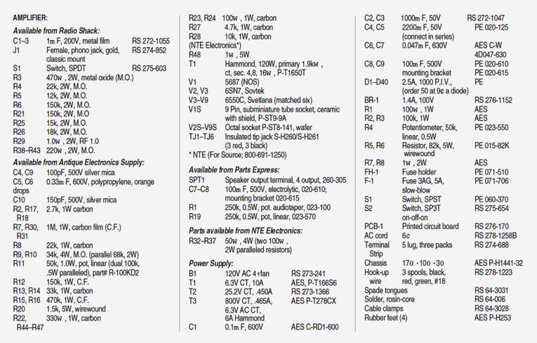
The circuit diagram of the amplifier is shown in Fig. 1, and the parts list in Table 1. The design features six 6550s connected as triodes preceded by a duo-triode long-tailed phase inverter and a triode first stage, both paralleled. The advantages of triodes in the amp’s output stage are reduced distortion and improved frequency response and damping characteristics.
The amplifier requires a 1.8V (RMS) drive signal for 100W output with a modest 15dB of feedback, an amount that provides distortion below 1% at full output (except 1.6% at 15kHz). This small amount of feedback ensures the production of vocals and high frequencies at a very natural and realistic state.
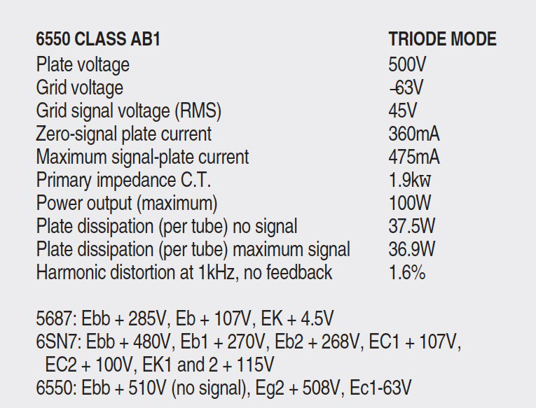
The 15dB of loop feedback reduced the amplifier’s distortion by 9dB at the 100W level at 1kHz. A review of the tube data in Table 2 reveals that the dissipation level of 37.5W is within the recommended rating for these tubes. I obtained the 100W triode operation by raising the bias of the 6550s to -63V DC, thus providing a 44V (RMS) drive signal to the control grids of the 6550s. No clipping occurred at the 100W level.
Driver Stages
The 5687 is used for the amp’s first stage (Fig. 1). The distortion of the paralleled 5687 with 6.0V (RMS) output signal (no feedback) is less than 0.3% from 20Hz–20kHz. Because of the very low plate impedance of the paralleled 5687, the frequency response has a flat output from 10Hz–20kHz at 6V (RMS), tapering to 5.8V (RMS) at 30kHz (not connected to the inverter). This is the widest bandwidth of any tube I’ve tested. It is an excellent driver for the paralleled 6SN7 long-tailed inverter.
The noise of the 5687 is 2.2mV with the filament operating at 5V AC, and 1.8mV at 5V DC (measured at the normal 6.3V AC, the noise is 5.4mV). I reduced the heater power on the 5687 because it is excessive for an audio application. I believe the original application of this tube was for computers. Its heater power operating at 6.3V and 0.9A is equivalent to that of a 6L6, which for an audio driver application is excessive. With 5V (AC or DC) applied to the 5687’s heater, the heater current is 0.8A (or 4W), which compares favorably with the 3.6W heater power of the 6SN7.
The long-tailed phase inverter using push-pull parallel 6SN7s offers reduced phase shift and a stable feedback loop by eliminating a stage of amplification. I used push-pull parallel operation of the inverter to obtain lower distortion, a better physical layout of the discrete components, and isolation of the grid- and cathode-driven sections. The phase inverter has unequal output voltages because of the slightly higher gain of the grid-driven section. The balance of these output voltages is obtained by shunting the 34kW resistor (R9) with a 150kW resistor (R12), and is maintained with five different 6SN7s, so this should provide a permanent fix.
DC Balance
You obtain DC balance on both sides of the inverter by adjusting potentiometer R19 for a zero indication at the junction of C2 and C3 and pin 1 of the 5687. (If you question the addition of this circuit to the inverter, please read my reply to Richard Trim’s letter in GA 4/98, p. 59, and refer to Norman Crowhurst’s article, “Realistic Audio Engineering Philosophy,” in Audio Anthology, Vol. 5, pp. 64–5.)
An antiringing R/C network (C4 and R8) is connected to the signal grid of the inverter. The distortion of the inverter stage, measured on either side (no external feedback), is less than 0.4% from 20Hz–20kHz at 44V (RMS) output. I made this measurement with the 6550s disconnected from the output of the inverter.
Allowing for the push-pull effect and resulting second-harmonic cancellation, the total harmonic distortion (THD) for the inverter is approximately 0.3%. The frequency response of the driver stage (5687) and inverter (6SN7s) with feedback applied is flat from 20Hz–70kHz with the inverter connected to the 6550s. The 44V (RMS) output drives the six 6550s to their full rated output of 100W.
As far as I know, the long-tailed inverter was first paralleled in the circuit application described in my article, “70 Watt Low-Distortion Triode Amplifier,” which I mentioned at the beginning of this article. The paralleled driver stage and long-tailed inverter provide a simple, stable, wide-bandwidth circuit that should become a standard for all high-end commercial audio amplifiers. It is better than any circuit I’ve constructed, and I rate it A-plus when measured against other audio driver systems.
Output Stage
The six 6550 triode-connected output tubes operate Class AB1 under the conditions shown in Table 2. The fixed-bias voltage of the 6550s’ grids is raised 30% (from -46V DC to -65V DC) above that normally recommended in the tubedata sheets. The increased bias voltage permits an increase in the signal-driving voltage from 34V (RMS) to 44V (RMS).
This, plus the increased plate-current swing, allows the output stage to provide an output of 100W (RMS). You obtain the 6550s’ static plate-current balance by adjusting the 50kW “balance control” in the output tubes’ grid circuit. Balance is obtained when a minimum voltage differential (no signal) exists between the 6550 plates (TJ1 and TJ2). If you have a distortion meter, I suggest you adjust the balance control for minimum distortion at 35Hz. To ensure balance, use matched 6550s. I recommend ordering six of them, all matched, plus one extra as a spare.
To further assist balancing the 6550s, I inserted a 1.0W resistor (R31) in the cathode of one of them. This permits interchanging them until you obtain the best balance. You set the plate current by adjusting the bias-voltage potentiometer R4 (Fig. 2). A static plate current of 60mA is the correct operating current, and no color of the 6550s’ plates is evident at this level. A .06V indication corresponds to a 60mA plate current.
The amplifier is very stable at low frequencies, as evidenced by the distortion measurement at 30Hz and 35Hz (no drifting or fluctuating of the meter). To further ensure the 6550s’ stability, I inserted a 330W carbon resistor in the grid circuit of each leg of the outboard stages, and 1MW resistors from grid to ground of the last two outboard 6550s (V6 and V9).
The plate current of the six 6550s is measured across a 1W resistor (R48) at test jacks TJ3 and TJ4 (Fig. 1). A 0.1V DC indication corresponds to a 100mA operating current. A typical reading is 0.36V.
The resistors connected to the control grids, screen grids, and plates of the 6550s are necessary to prevent oscillation of the output tubes. The screen and plate resistors are paralleled 2W metal-oxide. To ensure stable operation of the amplifier, you must connect the inverse feedback loop to the output taps in use.
For example, when using the 4W tap, connect it to resistor R27 and capacitor C10, and when using the 8W tap, you connect it to resistor R28 and capacitor C9. If the amplifier requires the use of either 4W or 8W outputs, you must incorporate switch S1, but you can omit it if you use the amp with only one of these outputs. You must connect the secondary windings of the Hammond output transformer in a series configuration as shown in Fig. 1. If oscillation occurs when the amp is turned on, reverse the transformer’s primary plate leads.
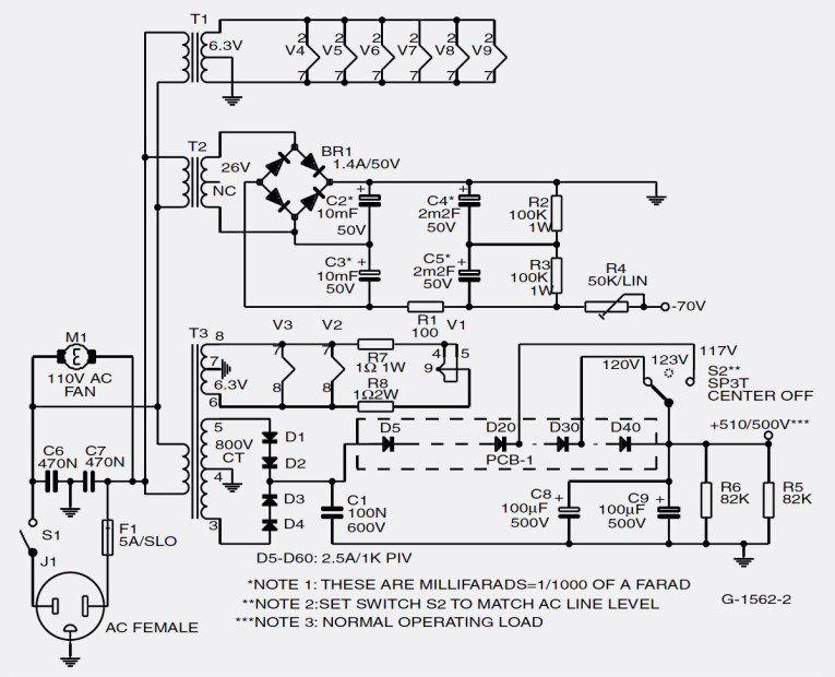
Amplifier Power Supply
The circuit diagram of the power supply is shown in Fig. 2, the parts list in Table 1. The bias supply (-70V DC) uses transformers T2 and full-wave bridge rectifier BR-1. Capacitors C2 and C3 supply voltage doubling. Resistor R1 provides decoupling, and resistors R2 and R3 bleed the supply. Potentiometer R4 sets the bias to the 6550s. Capacitors C4 and C5 provide final filtering, which limits the AC ripple to 0.1V AC. The filament transformer (T1) provides the 6.3V AC to operate the six 6550s.
The plate-supply transformer (T3) provides the 6.3V AC required to operate the two 6SN7s and 5687 heaters. Two 1W resistors (R7, R8) are placed in series with the 5687 heater to provide approximately 5V AC operation. The transformer’s high-voltage winding feeds a full-wave diode rectifier (CR1/2 and D3/D4). The 36 (D5–D40) series-connected diodes (2.5A, 1kV) decrease the +530V DC to +510V, with an AC line voltage of 123V AC.
To manage the variations in the AC line/DC output of the plate supply, add an on-off-on switch S2 (Fig. 2). This switch maintains the 510V DC (no load) output of the plate supply, with AC line voltages of 117, 120, and 123V. Turn the power off whenever you switch S2 (the diodes are available from Parts Express for 9¢ each). Using series-connected diodes does not impair the regulation of the power supply, which is affected only by the very good regulating capabilities of the power transformer. R5 and R6 are paralleled bleeder resistors, primarily to protect the electrolytic capacitors. Capacitors C1, C6, and C7 eliminate AC hash. The AC ripple of the 500V DC output of the power supply is 1.6V.
Amplifier Performance
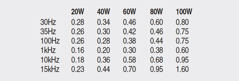
The amp’s performance data is presented at its maximum operating levels. At 10W, from 20Hz–15kHz, the distortion is less than 0.16%. The harmonic-distortion data is presented for 20, 40, 60, 80, and 100W operating levels (Table 3). I made the amplifier-distortion measurements using both the 4W and 8W output taps, but the 4W -tap results are the same as those for the 8W tap, so they are not shown.
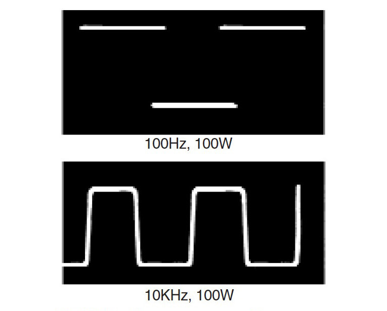
The square-wave oscillograms (Fig. 3) are shown for the amp’s 100W output. The 100Hz and 10kHz square waves exhibit slight low- and high-frequency rolloff, while the 1kHz square wave (not shown) is reproduced almost perfectly. No high-frequency ringing occurred with the amplifier reproducing the 10kHz square wave, even with a 0.1m F capacitor shunted across the transformer secondary—indicating good high-frequency stability.
The amplifier is also stable at low frequencies. The response is flat from 10Hz–40kHz at 12W, and flat from 20Hz–20kHz at 80W. At 100W, the output is flat from 30Hz–16kHz, tapering to 91W at 20kHz. The noise, measured with the input open, is 3.9 and 5.7mV at the 4W and 8W taps, respectively. The performance specs speak for themselves. Here is an amplifier you can build for moderate cost and with few construction problems. Test equipment is listed in Table 4.
Construction Tips
I used point-to-point wiring. Most components are tied to the five-pin terminal strips, the center terminal is ground, and components requiring a ground are tied to this ground post. The 36 series-dropping diodes in the power supply required the use of a PC board. The secondary windings are stripped and soldered, so I recommend that you not cut and restrip them. The preferred method is to snake them around the output transformer’s 10-32 holding screws and secure the wires with cable clamps and 10-32 nuts. All the transformers are secured with 10-32 fasteners.
The bias supply requires two terminal strips, and the filament transformer one. Seven additional terminal strips are used in the amplifier. Each side of the paralleled 6550 filaments has its own separate filament wires returned to the 6.3V output winding of the transformer.
A short ground path is provided for the 6SN7s’ ringing, grid, and cathode circuits. You must ground (at both ends) the shielded cable connecting J1 to the input of the 5687. Use mounting feet on the bottom of the amplifier chassis to give good under-chassis air-flow. I used a Radio Shack 65CFM fan (F1) to ensure adequate cooling of the output tubes. It does a good job, and the amplifier runs cool. I also made numerous holes in the chassis to further increase air circulation (Photo 2).
SOURCES
Antique Electronics Supply (AES)
Parts Express (PE)
NTE Electronics
About The Author
After an army stint in Korea as a sergeant in charge of a radio-repair group, Joseph Norwood Still worked in technical and engineering capacities for many companies, including Philco, Sylvania, Boeing, General Dynamics, Xerox, Lockheed, Sperry, and Westinghouse, which sent him to Iran, Venezuela, and Saudi Arabia. He has designed vacuum-tube test sets, written many articles on technical and audio subjects, and, as evidenced by this article, enjoys designing and building his own audio systems.
This article was originally published in Glass Audio 3, 2000