This is determined by the target B in the gap, the gap width, and the gap height. For any desired maximum flux, there is a minimum pole diameter. The maximum flux can be defined by the saturation point of the steel (Bmax) used in the pole. It can also be a lower value that reflects a linear operating range on the BH curve to minimize inductive distortion, an important factor in subjective sound quality.
PoleSolver is a design tool from Redrock Acoustics that makes this calculation quick and easy. Users simply input the target Maximum Flux, Gap B, Gap Height, Gap Width, and Vent Hole Diameter. With this data, PoleSolver will then calculate the minimum pole diameter to match the targets. PoleSolver can also calculate an array of diameters based on a range of Gap Heights and Gap Widths.
PoleSolver Tutorial
What makes a great loudspeaker design? As a good friend who has been in the industry for a very long time puts it, “It’s all about dBs per dollar.” In other words, the least expensive way to meet the performance goals is the best solution.
Design Goal
If you accept this idea, then you can translate it into engineering terms by acknowledging that the best design can be defined as being the one with the smallest diameter voice coil that will meet the goals. A smaller diameter voice coil will always result in a lower mass, a smaller motor magnet, and ultimately lower cost.
The voice coil diameter lower limit can be determined by either heating (thermal compression/power handling) criteria or by a target motive force (BL2/Re).
Ultimately, it’s the balance between the two that will make an ideal design. Coming up with the smallest coil diameter that can meet a target motive force is a fairly complex task. Half of this problem is about wire gauge or how much of it you need, which is the “L” and “Re” part of the equation. Essentially, this can be simplified by reducing it to how much conductor (wire volume) you put in the gap.
The other half of this problem is the actual “B” value. “B” is the integrated gap flux that induces current into the conductor. Increase either factor B or L and you increase motive force.
The conductor part of the design is determined by heating, mass, materials, and other physical properties that can be defined by pretty simple calculations. The “B” part is a bit more complicated and is determined by the “magic” laws of magnetics. Permeance paths, saturation, and flux density are all concepts that are rather complex to deal with, even if you use them on a daily basis. Reducing them to the intuitive level, you can simply use a “current” analogy: “How big does the wire need to be to carry the current that you want?” In the case of the magnetic circuit: “How much steel do you need to get the integrated gap B you require?”
The term “integrated gap B” simply refers to the average B in a given gap with a given height and width.
From a cross-section view of a speaker motor, this would be the “area” of the gap. Essentially the bigger the gap area the more flux (magnetic current) you need flowing through the metal parts. At some point the flux will exceed the ability of the steel to carry it. This limit is called the “saturation” point and is specified as the material’s “Bmax.” In reality, Bmax is a transition point on the material’s BH curve, but for simplified calculations it is a good reference.
Below this value you are getting the best mix of magnet volume to resulting B. Above this value even a large increase in magnet volume will give only a relatively small increase in B. If it’s all about dBs per dollar, then you want the smallest magnet to give the highest B value.
From this, you can conclude that the smallest functional pole diameter will yield the smallest magnet and lowest cost design.
Spreadsheet Solution
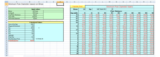
Wouldn’t it be nice, then, to specify the target gap B and gap area, and then automatically calculate the minimum pole diameter (based on Bmax)? This is essentially what the PoleSolver Excel sheet does. You input a target gap B, the top plate thickness (gap height), gap width, vent hole diameter, and Bmax, and Pole Solver then calculates all of the background magnetic formulas and outputs the minimum pole diameter required.
PoleSolver can also calculate a matrix of minimum pole diameters based on a range of plate thicknesses and gap heights. Take a look at a worked example. The target will be a gap B of 1.5 tesla, which is on the high side of what you can expect from traditional ceramic-based motors.
If you are attempting to build a relatively high sensitivity speaker, it would be a good place to start. If this is the goal, then it’s a given that you want a very thin (0.5mm) two-layer coil for good high-frequency response (low inductance) and a relatively thin front plate of 4mm. For this example, I will specify that this design will not have a vent hole. The value used for Bmax will be the established maximum flux value for 1008 type steel, which is about 1.8 tesla.
Entering these values into the PoleSolver sheet (Fig. 1), you quickly see that the minimum pole diameter is 19.45mm. If you want to see other possible combinations of plate thicknesses and gap widths to reach the target B, you can use the matrix solver. This is a quick method that will determine whether other coil options would yield higher motive force by using thicker front plates. For example, if you wanted a 6mm front plate, the minimum pole diameter would increase to 26mm for the same Bmax value. An 8mm plate would yield a 33mm pole diameter.
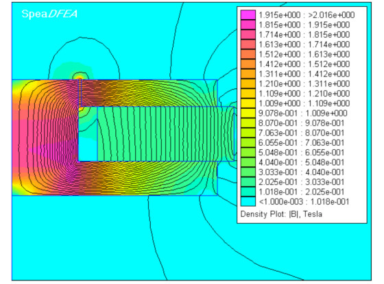
As a check for accuracy, the magnetic FEA computer simulation (using the SpeaDFEA tool) shows the 19.45mm design results in 1.8 tesla through the pole as predicted and an integrated gap B of 1.5 Tesla (Fig. 2).
At www.redrockacoustics.com there’s also has a wide variety of other tools and tutorials regarding loudspeaker design.
Originally published by Voice Coil, August 2010