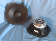

Photo 2 shows the sample pro sound midrange driver MAG submitted. This is one of my favorite pro sound midrange formats. My first experience with a short XMAX curvilinear paper cone and flat surround pro midrange was the Audax Professional Midrange available in the 1980–1990 era. I reviewed this midrange in an early issue of Voice Coil and later incorporated them into a three-way keyboard monitor I built for my studio. I still have these speakers, but the foam surrounds disintegrated several years ago. Fortunately, Philippe Lesage, Audax’s former chief engineer designed these drivers. He left Audax to form PHL Audio, which still makes almost the same driver. So, I was able to change the drivers without making any crossover changes. The MAG’s M0610 has a similar format, which is exciting.
The M0610’s features include a cast-aluminum frame, a lightweight curved profile uncoated paper cone, a 2” diameter uncoated paper dust cap, and a 1.5” (38-mm) diameter voice coil wound on a Kapton former with edge wound copper-clad aluminum ribbon wire. Compliance is provided by a flat foam surround (similar to the Audax and PHL models) and a 4.5” diameter flat cloth spider. A 110-mm × 15-mm detachable self-centering strontium ferrite magnet with a black coated back plate powers the unit. Last, the voice coil tinsel lead wires terminate to a standard pair of solderable terminals.
I clamped the driver to a rigid test fixture in free air and used a LinearX LMS analyzer and VIBox to produce voltage and admittance (current) curves at 0.3, 1, 3, and 6 V. I post-processed all eight 10-Hz-to-20-kHz 550-point stepped sine wave curve pairs for each sample and divided the voltage curves by the current curves, which created the five impedance curves. I applied the LMS phase calculation procedure to each impedance curve and imported the data along with the voltage curve for each sweep into the LEAP 5 Enclosure Shop CAD program.
I used 1-V free-air curves to create the LEAP 4 TSL model. I selected the complete curve set, the multiple voltage impedance curves for the LTD model, and the TSL model’s 1-V impedance curves in LEAP 5’s transducer derivation menu and created the parameters for the computer box simulations. Figure 1 shows the 1-V free-air impedance curve. Table 1 compares the LEAP 5 LTD and TSL data and factory parameters for both M0610 samples. The M0610 6.5” midrange’s T-S parameter results had some variations worth noting. First, the XMAX quoted by MAG includes a large portion of the fringe field. (The Klippel data confirmed this information.)
I also used the physical XMAX numbers derived from the published gap and voice coil height numbers. While there are variations in the VAS and QTS, this driver is not intended to be operated in the piston range, and the consequence of these variations is rather minimal. The reason I publish T-S data and box simulations on a driver like this is mostly to establish the enclosure resonance and QTC to help make passive crossover decisions. However, with this pro sound driver, it’s more likely that the device will be used with an active crossover, making the data less important. That said, I used the LEAP LTD parameters for Sample 1 with two sealed enclosure sizes to program computer enclosure simulations. This included a 0.15-ft3 closed box with 50% fiberglass fill material and a larger 0.3-ft3 sealed box alignment also with 50% fiberglass fill material.


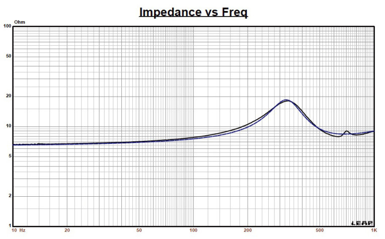

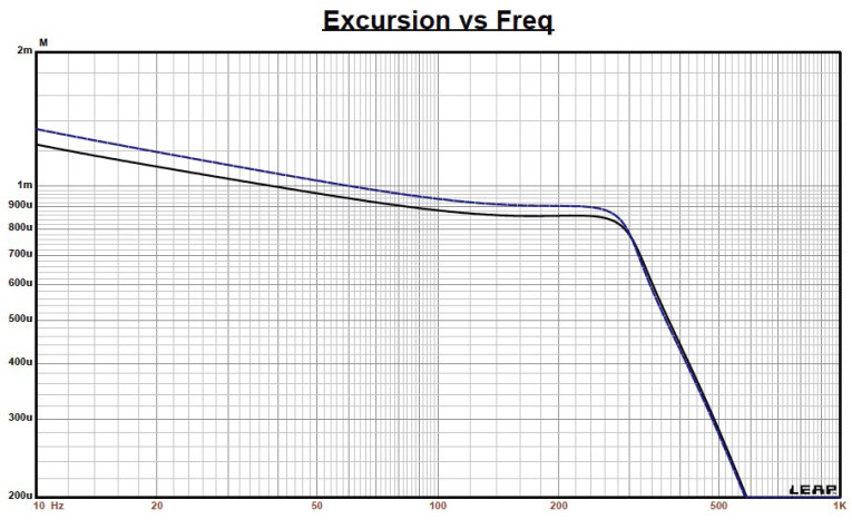
Figure 2 shows the M0610 midrange’s results for the two sealed boxes at 2.83 V and at a voltage level sufficiently high enough to increase cone excursion to XMAX + 15% (1.15 mm for the M0610). This calculation resulted in a 309-Hz F3 frequency with a 0.93 QTC for the 0.15-ft3 sealed enclosure and –3 dB = 297 Hz with a 0.86 QTC in the 0.3-ft3 closed-box simulation. Again, the midrange’s piston range is generally not particularly important.
Figure 3 shows the 2.83-V impedance in the 0.3-ft3 closed box compared to the free-air impedance and there is very little difference. Increasing the voltage input to both simulations until the maximum linear cone excursion was reached resulted in 111.5 dB at 20 V for the smaller sealed enclosure and 111.2 dB with the same 20-V input level for the larger sealed box Figure 4 and Figure 5 show the 2.83-V group delay curves and the 20-V excursion curves.
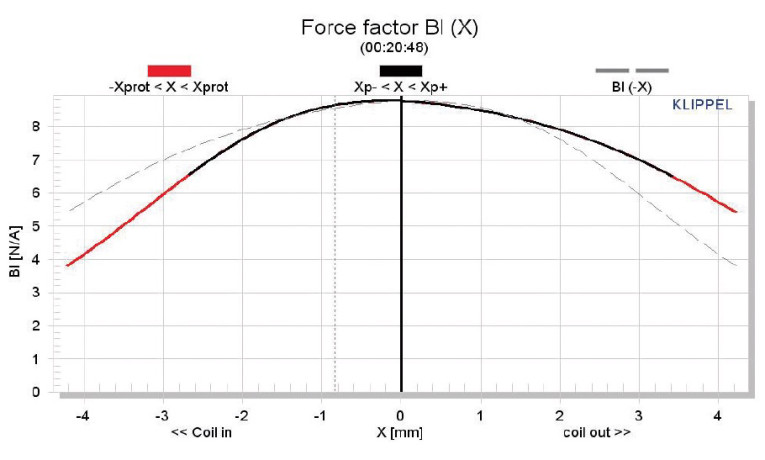
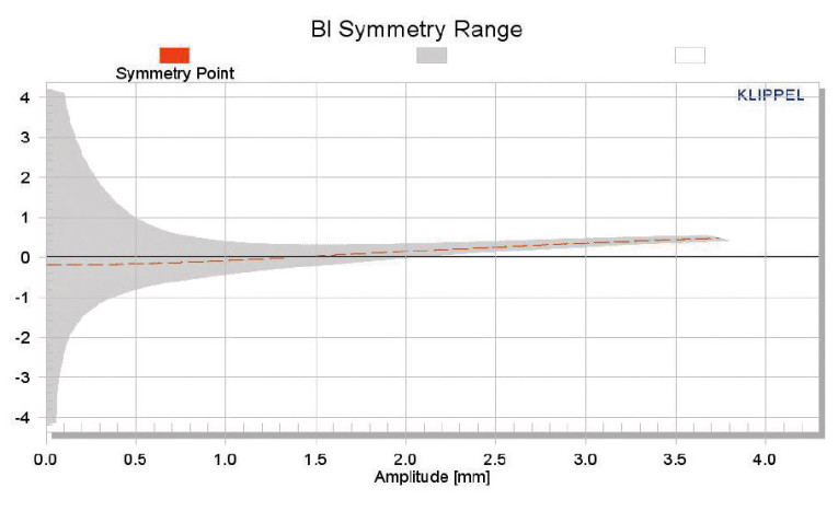
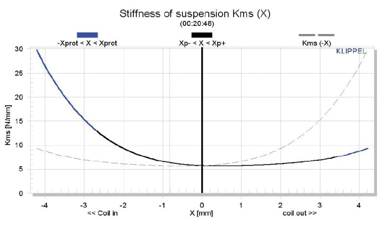

The MAG M0610’s Klippel analysis produced the Bl(X), KMS(X) and Bl and KMS symmetry range plots shown in Figures 6–9. Figure 6 shows the MAG M0610’s Bl(X) curve is fairly narrow, but as you would expect for a short to moderate XMAX (1-mm) pro driver and is moderately symmetrical with almost no offset. The Bl symmetry plot in Figure 7 shows no offset out to the M0610’s physical XMAX, which is not a problem since it is not really going to operate in the piston range. Figure 8 and Figure 9 show the M0610’s KMS(X) and KMS symmetry range curves, respectively.
The KMS(X) curve is rather asymmetrical. However, this is just an affectation of the unusual flat-foam surround used in this type of device. Looking at the KMS symmetry range curve, there is obviously a lot of forward coil-out offset, but for this to be relevant, the cone must be moving. With a fourth-order LR active high-pass at perhaps 500-Hz motion, this won’t be an issue. Again, I am displaying this information to characterize the performance of a flat surround, which you will only see in the pro sound midrange category. The M0610’s displacement-limiting numbers calculated by the Klippel analyzer showed the XBl at 82% (Bl = 2.3 mm) and the crossover at 75%, CMS minimum was 1.5 mm, which means the compliance is the most limiting factor at the 10% prescribed distortion level, but even this is beyond the driver’s physical XMAX!
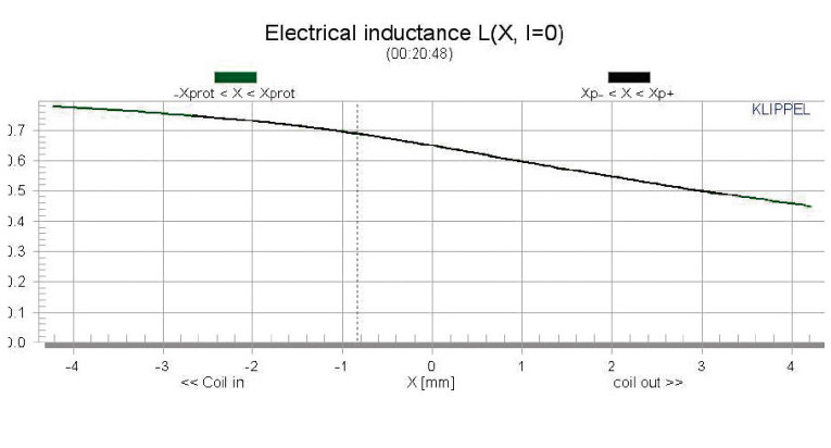
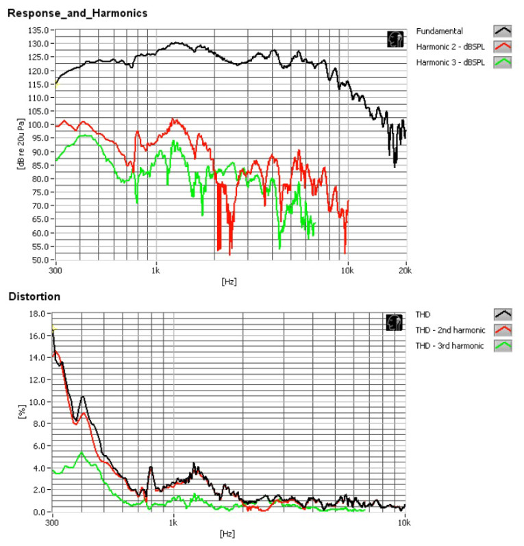
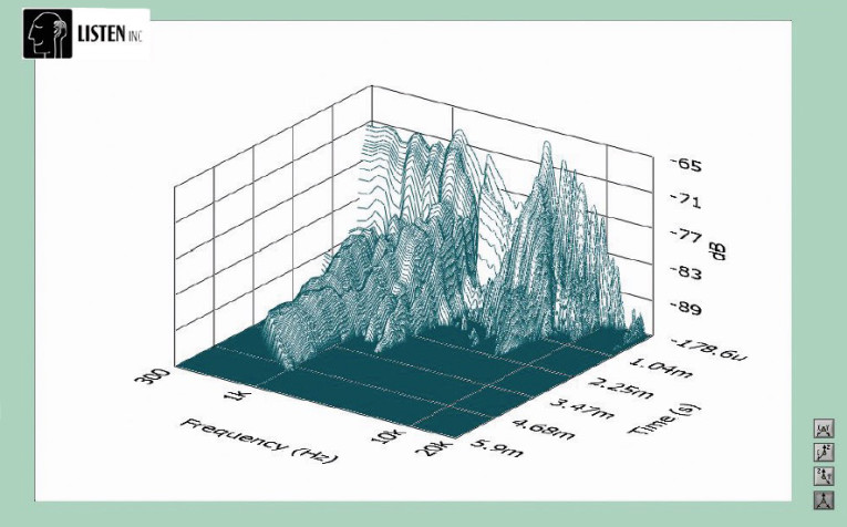
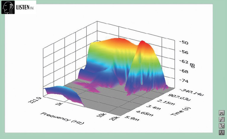
Figure 10 shows the M0610’s inductance curves L(X). Inductance will typically increase in the rear direction from the zero rest position as the voice coil covers more pole area, which is not what you see with this style of motor. From XMAXOUT to XMAXIN, the inductance range is only 0.7 to 0.6 mH, which is only a ±0.06-mH delta.
Next, I used the Listen SoundCheck AmpConnect analyzer for distortion measurements. I mounted the M0610 in an enclosure and used a noise stimulus to set the SPL to 104 dB (8.76 V) at 1 m, which is my standard for pro sound products. Then, I mounted the driver in free-air and placed the microphone at 10 cm. The M0610 produced the distortion curves shown in Figure 11. Following the distortion measurements, I again mounted the M0610 in an enclosure with a 8” × 12” baffle to take the impulse measurement. I imported the data into Listen’s SoundMap software, windowed to remove the room reflections, and produced the cumulative spectral decay (CSD) waterfall plot shown Figure 12. Figure 13 shows the Wigner-Ville plot.
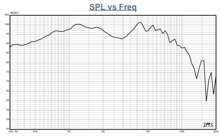
For the remaining SPL measurements, I used the same enclosure used with the impulse response. Then, I used a gated sine wave method to measure the driver frequency response on- and off-axis from 300 Hz to 20 kHz with a 100-point resolution at 2.83 V/1 m. Figure 14 shows the M0610’s on-axis response, which yielded a smooth rising response out to 2 kHz followed by a 4-dB depression at 3 kHz peaking at 4.3 kHz just prior to the low-pass roll-off. Figure 15 shows the on- and off-axis frequency response at 0°, 15°, 30°, and 45°. A –3 dB at 30° result with respect to the on-axis curve occurs at 2.2 kHz, which is a typical 2.5 to 3 Hz crossover for 6.5” drivers with 1” domes. When used with a horn, anywhere lower than that is appropriate.
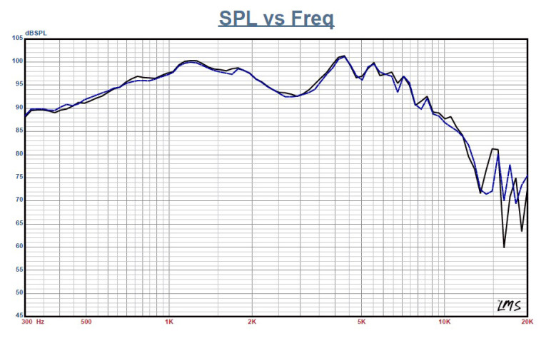
Figure 16 shows the M0610’s two-sample SPL comparisons, with both samples closely matched. The M0610’s fit, finish, and build quality is very nice, suggesting MAG should be a good contender in the pro sound driver arena. To learn more about the MAG M0610 and other pro sound drivers, visit mag-audio.com

This article was originally published in Voice Coil, November 2013.