This circuit enables the full galvanic isolation of sound frequency signals with optical transmission in excellent quality, eliminating interference.
When you connect audio components, interference may occur from various power and signal grounds.
For safety reasons, screenings are interconnected through the protection ground and the protection wire. The circuit that is formed this way opens a free path to the noise and hum from the power supply network and to the interference that originates from computers and other high-frequency generating equipment.
By eliminating protective grounds, you could reduce the problem, but this is not allowed, because all power equipment must have a protection ground. Disabling the already existing protection ground can be hazardous.
But it is not necessary to sacrifice safety to construct a system free of ground loops and annoying hum. By separating the reference points, you eliminate the potential differences and disturbing current loops, thus hindering hum and noise.
For many decades the solution for eliminating interference was the isolating transformer; however, this solution was rather problematic. You can only realize the complete audio frequency response with an extra compensated amplifier. This frequency response can be worsened by possible resonance responses; furthermore, the compensation amplifier is sensitive to hum from the power supply network. Correct impedance matching requires additional amplifier stages, resulting in expensive equipment.
It was only with the development of optoelectronics that a new solution has emerged. With an ordinary optocoupler, you can transmit only digital signals. However, the characteristics of the optocouplers have been improved so that they enable linear transmission of the applied signals.
The Applied Optocoupler
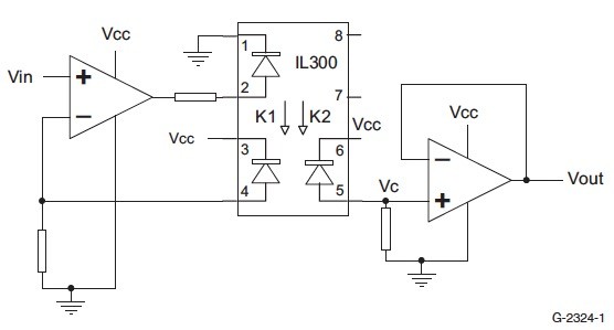
In this audio frequency application, I have chosen the IL300 linear optocoupler, which consists of an IRLED that is irradiating an isolated feedback and an output PIN photodiode in a bifurcated arrangement. The feedback photodiode captures a percentage of the LED’s flux and generates a control signal that can be used to servo the LED drive current. This technique compensates for the LED’s nonlinear characteristics.
The output photodiode produces an output signal that is linearly related to the servo optical flux produced by the LED.
A typical application circuit (Fig. 1) uses an operational amplifier at the circuit input to drive the LED. The feedback photodiode sources current to R1 connected to the inverting input. The output photodiode is connected to a non-inverting voltage follower amplifier. The photodiode load resistor, R2, performs the current-to-voltage conversion. The photodiode is operating as a current source. The output current is proportional to the optical flux supplied by the LED emitter. The receiver diodes can be applied either as a photovoltaic or as a photoconductive source. In the case of the photovoltaic configuration, the linearity is better, there is less noise, and, as a result, the configuration is more stable. However, in the case of photoconductive mode, frequency response is better.
As in the case of sound frequency applications, there are no special requirements for the frequency response, so my choice was the photovoltaic solution. With IRLED, the best linearity can be obtained at drive currents between 5mA to 20mA. The LED is functioning in an optically controlled circuit, thus linearizing the light emission and minimizing the effects of aging and temperature changes.
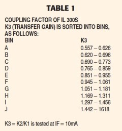
The photocurrent is proportional with the light intensity of the inner IR diode and feedback diodes. The IL300 is available in various groups according to light-transmission characteristics. This is marked with K3 coupling factor, which is actually the ratio of the coupling factors of the two photodiodes (K3 = K2/K1).
Table 1 shows the coupling factor of IL 300s, sorted into K3 bin, indicated by an alpha character that is marked on the part. The bins range from A through J. These optocouplers provide either an inverting or non-inverting transfer function, based upon the type of input and output amplifiers. The non-inverting input amplifier requires the use of a bipolar supply, while the inverting input stage can be implemented with single supply operational amplifiers that permit operation close to ground.
In order to achieve thorough isolation, the power supplies must be separated. Two kinds of applications have been developed. The first solution is standalone equipment with its own 110V AC power supply. The second solution is the installation of the galvanic isolator stage into the system, (e.g., an amplifier), and accordingly can be supplied with DC from the equipment itself.
Test Results
Ordinary audio levels: 775mV eff
Maximum audio levels: 1V eff (in and out)
Connectors: Stereo input and output Commercial phono-socket (transformer-fitted circuit) PCB mounting terminal block (for retrofitting)
Gain: 0dB
Frequency response: 20Hz…30kHz, practically linear
Distortion: <0.05% @ 1kHz, 775mV eff
Power on indicator: LED (first solution)
Supply voltage: 110V AC (first solution) / 14…28V DC (second solution)
Current drain: 35mA (second solution)
Circuit boards: 104 × 86mm PCB-single sided (transformer-fitted circuit) / 80 × 60mm PCB-single sided (for retrofitting)
Warning! Because the equipment operates at 230V, please heed the descriptions and instructions referred to in this section for life-safety reasons.
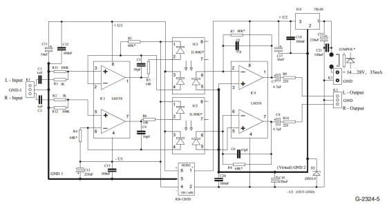
Principles Of Operation - First Solution
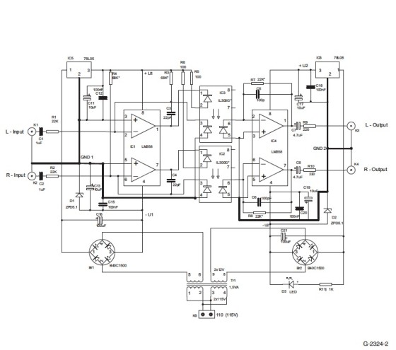
This solution is appropriate for applications external to the equipment because it is supplied from 110V AC (Fig. 2). A transformer with two separate secondary coils can be found in the power supply so the thorough isolation is assured.
The two power-supply sections have similar construction (the only difference is their regulators). After rectification and filtering, voltage regulations can be found for the input stage 78L05 and for the output stage 78L08. As both sides need an approximately symmetric supply voltage, this is achieved by zener diodes, implementing them in the ground leads of the regulators just mentioned.
As the power consumption is small, this can be easily implemented for production of the required −5V. Components C13, C15, C19, and C20 filter the noise from the zener diodes. At the regulator output, C11, C12, C17, and C18 filter the remains of probable hum and eliminate high-frequency components, thus minimizing the probable noise of the voltage regulator.
The preamplifier gets ±5V supply voltage, while the output amplifier is supplied with +8V and −5V. D3 LED, which is supplied through R11, functions as a power-on indicator. For the transmission of bipolar audio signals, the approximate bias of both OPs must be ensured. This can be achieved by the R3 (R4) resistors at the preamplifier and the photodiodes that function in photovoltaic mode in the optocoupler. The value of R3/R4 depends on the optocoupler’s K3 transmission factor, thus determining the symmetric signal transmission and the most favorable operating point of the IR diode, which in this case is approximately 10mA.
In the case of IL 300G, K3 = 1.1 (approximately); accordingly, the resistor value R3 (R4) = 68k.
The voltage of the photodiode is connected to the inverse input (IC1) as feedback, thereby stabilizing the operating point and supporting the distortion-free signal transmission. IRLED current is limited by R5 (R6) resistors. The preamplifier is functioning in inverse mode, but as the signal is connected to the inverse input, in-phase signal appears on the IRLED.
On the receiver side, the voltage generated on the photodiode is amplified by IC4. Balancing the operating point is required here as well, which is achieved with R7 (R8). These resistors set the feedback, determining thus the level that is identical at the input and the output. The full gain is 0dB. If required, you can set the amplification by changing R7 (R8). Components R9 (R10), which are found on the output, protect against overload and probable high-frequency noise. The amplifier is compensated (by neutralization) against noise with C3, C5 (C4, C6) capacitors. Because the equipment is designed for independent application,
commercial phono sockets are fitted at the input and the output.
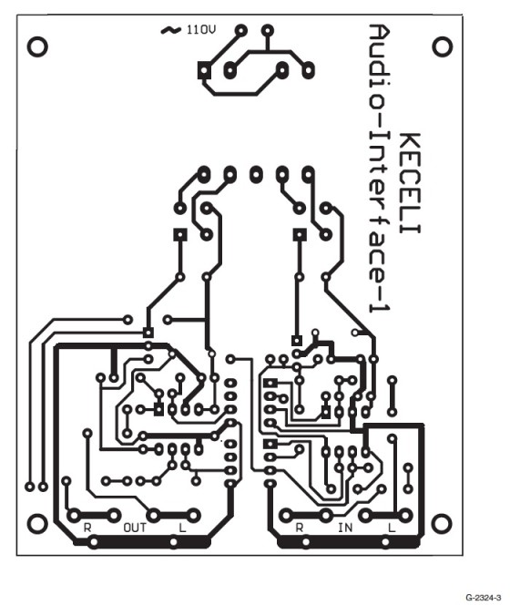
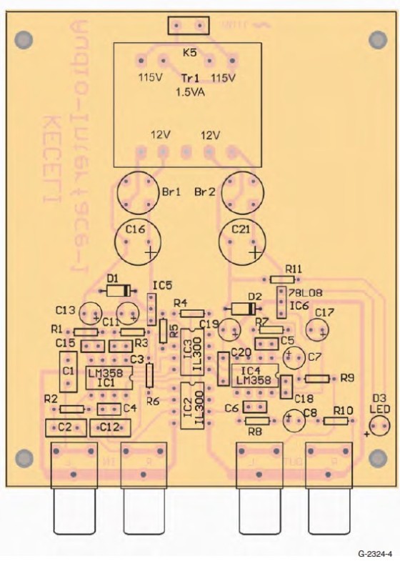
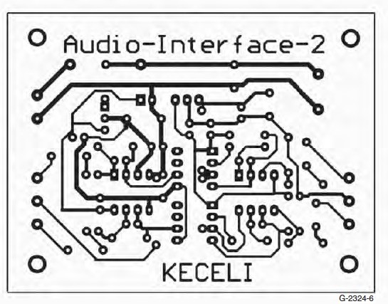
Circuit Assembly - First Solution
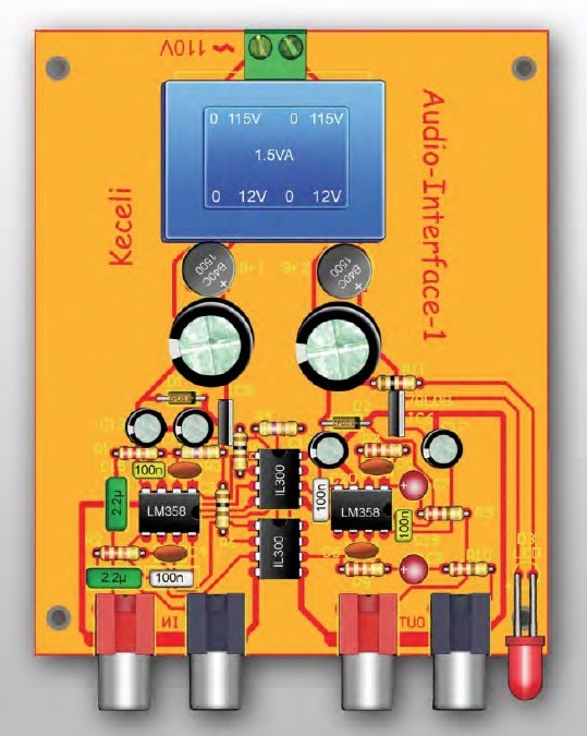
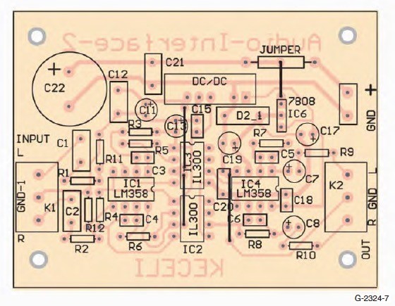
The PCB is a single-sided board as shown in Fig. 3. Figure 4 shows the placement of the components. The board is slightly longer, so the electrical network transformer can fit farther away from the amplifier components in order to avoid hum. All the components, the transformer, and the connectors are assembled on the PCB. There are no jumpers on the PCB.
After assembly, the equipment should function without any problem. By using the IL300-G optocoupler, there is no need for further adjustments after the assembly. Unless you use an optocoupler with specific transfer gain G, you must select the values of the resistors R3 (R4) on the basis of the coupling factor K3. The correct value for IL300 can be determined by calculation (refer to the IL300 product specifications), but it is better to ascertain it by measurement. For this test you need an oscilloscope and a tone generator.
An approximately 1V eff, 1kHz signal is applied to the input of the galvanic isolation amplifier. At the same time, the balance of the output signal is monitored by the oscilloscope. A perfect, symmetric, sine-wave signal, without clipping, must be adjusted on the output. This is carried out by temporarily changing the values of R3 (R4). In this case, you can replace these resistors with a serial combination of a 50Klin (Trim) potentiometer and a 22K resistor. (It is sufficient to carry out the measurements on one of the channels, thereby determining the value of the resistor.
You can fit the new resistors by soldering in both channels.) If required, you can modify the gain by changing the values of R7 (R8). Finally, you must mount the galvanic isolation amplifier in a suitable case, which can be either plastic or metallic. However, since the case is connected to the output ground, metallic is a more appropriate style because of the screening.
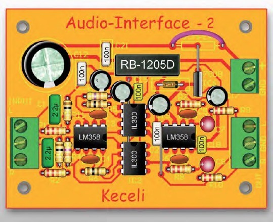
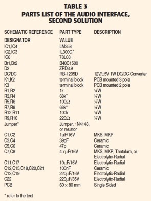
Principles Of Operation - Second Solution
The second galvanic isolation amplifier (Fig. 5) is planned for installation, e.g., in an amplifier or other equipment. It can be powered from a single ended, approximately 14−28V DC power supply, which is usually available from the power supply of the host equipment.
There is a significant difference in the supply circuitry of the two solutions. The output amplifier and the voltage stabilizer are similar as in the first solution. The difference is in the application of the symmetrical power supply stage. The middle point of the supply circuitry is used as the virtual ground, while the output ground is the negative side of the power-supply circuitry.
When installing, it is actually not necessary to connect both earthing conduits. The power supply of the preamplifier is generated by a DC/DC converter. This way a stabilized ±5V is produced from 12V, which is regulated by a 78L08 IC increased with the voltage of the D2 zener diode. Because a high frequency
DC/DC converter is used, more effective filtering is needed than in the first solution. This is why the capacity of the C13 and C19 capacitors is 220μF.
The input amplifier operates in non-inverting mode, which is different than in the previous solution. Hence the amplification of the input stage is lower. This should be compensated for on the output by increasing the value of R7 (R8) to 68k to achieve the target 0dB gain. The IC2 connection of the output stage is the same as in the case of the first solution. It is an inverting amplifier but with photodiodes in photovoltaic mode, hence there is no phase inverting.
Circuit Assembly - Second Solution
The PCB for the second solution is shown in Fig. 6. Figure 7 shows the installation of the components.
Because there are four jumpers on this board, you must first solder these in. The order is important because some jumpers are placed under the ICs. When finished, you can solder in the other passive components and finally the semiconductors.
There is a component marked “jumper” on the PCB in the power supply stage. If the value of the power supply is less than 28V, you can jumper this component or solder in a diode for polarity protection. In case of higher supply voltage, you can use a serial resistor. The current consumption of the isolation amplifier is approximately 35mA, and the serial resistor must be designed accordingly. The applied DC/DC converter does not cause any interference.
After assembling, the isolation amplifier should function immediately. If an optocoupler with different transfer gain is used instead of the one indicated on the drawing, the values of R3 (R4) must be as outlined in the first solution. If needed, you can change the values of R7 (R8) to achieve higher gain. Because this module is planned for retrofitting, I applied screw terminal blocks as connectors.
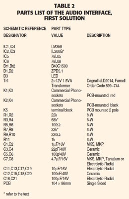
Click tables to zoom
References
IL300 Linear Optocoupler - applications
Texas Instruments production data information LM358.
ELV Journal 1999/3 (German)
Optischer Trennverstärker für analoge Audiosignale.
Elektor Journal 2003/3 (German)
Übertrager gegen Brummprobleme.
(English) - SAA3049 Replacement, pp 42–48.
This article was originally published in audioXpress October 2004.
About the author
Jenoe Keceli is a long-time electronics enthusiast with 40 years of experience. His main fields of interest are designing and building tube and transistor power amplifiers. He has much experience with sound and disco equipment. His articles have been published in electro technical journals. He now runs his own firm, where he builds, repairs, and gives advice.