“Headphone Testing (Part 1)” published in the December 2011 issue of Voice Coil, covered the basics of analog headphone testing: correction curves and fixturing, choosing hardware (ear simulators and couplers), the different requirements for testing in R&D vs. production, and the various essential measurements such as frequency response and distortion.
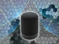
Analog headphones are relatively straightforward to test because there are only two electro-acoustic transducers to measure. Headphones with built-in electronics, such as digital headphones (including Bluetooth and USB), and noise-canceling headphones are harder to test because the electronics and transducers need to be tested together as a complete system. In this article, test considerations for such headphone systems and the practicalities of testing them are discussed.
Testing Digital Headphones
Headphones with digital connectivity add complexity to audio testing. In addition to testing the acoustic transducers, the digital circuitry must also be considered. The fundamentals of analog headphone testing (the use of artificial ear simulators and couplers, the principals of repeatability vs. realism, and the tests that characterize the device) are the same, but the test signals must pass through the headphone electronics, which can greatly influence the test results.
The principal distinction of digital headphones is that they contain a D/A converter and often DSP circuitry as well as a headphone amplifier. This means that unlike an analog headphone, where measurements are being conducted only on the electroacoustic elements, the measurements for digital headphones are being performed on the whole system which comprises everything from the digital signal to the acoustic output of the transducers. While it is certainly possible to isolate and test each of these components on its own, it is also very important to understand the intricacies of testing the complete device.
Managing Connectivity
The initial challenge of testing digital headphones is managing connectivity. The test system must be able to communicate directly with the device. A software-based system is ideal because it can communicate directly through the computer’s USB interface to the USB headphone, which will appear in the operating system along with other audio devices. Test signals can be sent digitally and the acoustic signals can be analyzed synchronously. If a hardware-based system is used, an extra program is usually required to connect the test system to the device under test.
Bluetooth headphones, however, require an additional interface for the computer to connect to the device under test. This may be a hardware Bluetooth communication box or a simple Bluetooth dongle, either built into the computer or externally connected by USB (see Figure 1). Bluetooth interfaces cause transmission delays in the audio chain. The test system must be able to account for these delays in order to take meaningful measurements. Some test systems can use an auto-delay algorithm that looks at the system’s impulse response to calculate the delay and remove it from the measurement, if necessary.
Frequency Limitations
It is also important to be aware of frequency range limitations when designing tests for Bluetooth devices. Bluetooth devices typically operate at low-sampling rates of either 8 kHz (narrow band) or 16 kHz (wide band). These sampling rates limit the frequency range (because of the Nyquist frequency) to significantly narrower than analog headphones or even USB headphones. For example, a Bluetooth device with an 8-kHz sampling rate will only play audio up to slightly less than 4 kHz. Such limitations need to be considered when designing the test specifications. It can also be interesting to test the Bluetooth device beyond its cut-off frequency to see how well its anti-aliasing filter suppresses out-of-band signals.
Test Signals
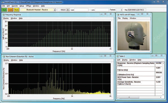
Bluetooth presents a further challenge in that sine waves are not always transmitted accurately. When this occurs, alternative stimulus signals must be considered. Broadband noise is one possibility, but because of noise suppression circuits in some devices, this may not be a practical solution. A multitone signal, where several frequencies are played simultaneously, is another option. This produces a very fast frequency response measurement and is immune to the sudden dropouts that can occur in Bluetooth transmission. The downside of this test signal is that traditional harmonic distortion cannot be measured. Yet another possibility is the use of speech or music signals. These real-world audio signals transmit very well over Bluetooth, but their downsides are that they typically require long-term averaging and cannot be used for harmonic distortion measurements. If distortion measurement is required, non-coherent distortion may be measured using any test signal. This technique compares the input and output power spectrums to measure the non-coherent power and calculate the distortion plus noise (see Figure 2).
Measurement Units
Traditional analog headphones are tested with a stimulus level that is rated in terms of voltage or power. The sensitivity is also specified in these units such as dBSPL / mW. When testing headphones with USB or Bluetooth connectivity the stimulus is simply a digital signal whose level can be expressed in terms of digital full scale. The sensitivity is, therefore, expressed in dBSPL/FS. Manufacturers sometimes choose to relate these signal levels back to voltage, which can be done if the characteristics of the D/A circuit are known. In such cases, the gain of the built-in headphone amplifier chip must also be accounted for.
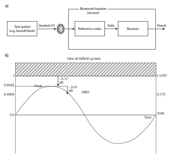
Another method used for relating these digital units back to the analog domain is through the use of a codec (see Figure 3). A-law and M-law are two codecs widely-used in Bluetooth applications that can translate the digital units into “virtual volts.” These codecs are most commonly used in telecommunications, especially for headsets.
Additional Measurements
In addition to the basic audio metrics discussed in the first article, there are some additional measurements that are of interest for digital headphones. The first measurement concerns the headphone amplifier. With analog headphones, THD and Rub & Buzz are typically sufficient for measuring distortion, but since their digital counterparts include built-in headphone amplifiers, it is advisable to also measure THD+N.
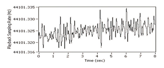
Alternatively, the noise can be measured on its own by sending a 0 FS signal to the headphones and analyzing the output. Other metrics specific to digital headphones are sampling rate accuracy and jitter. Sampling rate inaccuracy occurs when the digital clock on a consumer audio product is not entirely accurate, so the intended 44.1-kHz sampling rate may, for example, actually be 44.05 kHz. Jitter occurs when a signal fluctuates—for example, if a 1-kHz signal fluctuates between 999 and 1001 kHz (see Figure 4). Although the ear does not discern small sampling rate errors or jitter, there is a serious implication for testing.
Some digital tests involve comparing the output signal to the input signal. If the sampling rates are different, the difference in phase will cause the results to be meaningless. Generally, any measurement using time-synchronous averaging techniques is affected by jitter and sampling rate errors.
The most effective way to minimize the effects of such errors is to use a test system that features algorithms that compensate for this. If, however, your test system cannot accommodate this, there are a several other methods—such as power averaging, which ignores the phase response—that can be used to ensure accurate but less sophisticated results.
Noise-Cancelling Headphones
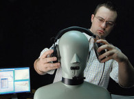
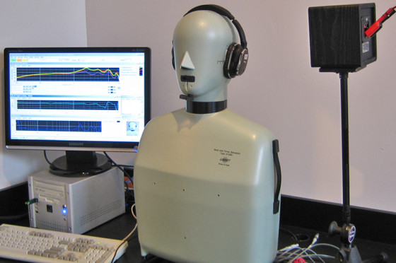
There are many different equipment configurations and environments that can be used for measuring noise-canceling headphones. As with conventional headphone testing, a head-and-torso simulator with artificial ears and pinnae provides the most accurate representation of the device’s performance. It is the best choice for performing these tests, but can be prohibitively expensive for some people.
Other options such as custom fixtures with artificial ear simulators are more affordable and will also work but will not be quite as true to the user experience.
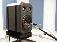
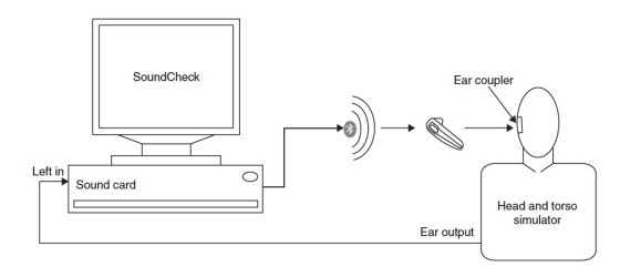
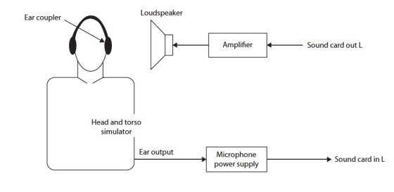
Whichever fixture type is chosen to hold the headphones, the entire setup must be placed in a noise field. The most sophisticated and realistic method would be to measure in a reverberation chamber or create a diffuse field using multiple speakers placed at various points in the room, with each one playing a noise signal that is uncorrelated to the others. However, for most purposes, a small single loudspeaker placed next to the head and torso’s ear at a distance of approximately 1’ is sufficient to generate meaningful data. Regardless of which equipment configuration or noise generation method is used, the general test method is the same: a known noise signal is played, and the passive and active attenuation characteristics of the device are measured. A typical test setup is shown in Figure 5.
The Noise Stimulus
Pink noise is an excellent choice for the noise stimulus, as its equal energy-per-octave characteristic means that it has enough low-frequency energy to simulate real-world noise conditions. If desired, the response of the single loudspeaker or the diffuse environment can be equalized to produce an acoustically flat signal at the head-and-torso ear, but this is usually not required.
The measurements made in a noise-canceling headphone test are relative, so it is not necessary for the absolute sound pressure of the noise at each frequency to be the same unless the device is sensitive to absolute sound level. Likewise, it is usually not necessary to correct for the artificial ear’s frequency response, although some may choose to do so.
The noise should be played for several seconds (usually somewhere between 5 and 15 seconds) in each measurement to allow the device to stabilize. The noise signal is captured through the artificial ear, and the test system measures the spectrum.
This spectral analysis is typically carried out using a Real Time Analyzer in one-third octave bands, which generates data that is more representative of how a human ear would hear the signal than using a standard FFT linear resolution analysis.
The Test Procedure
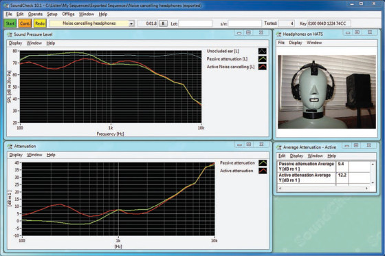
A noise-canceling headphone test procedure can be broken down into three measurements and three calculations. First, the headphones are removed from the head and torso, the noise signal is played, and the spectrum measured through the open ear. This un-occluded ear spectrum is used as the baseline for the noise. Next, passive isolation is measured by placing the headphones onto the head and torso, playing the noise signal again, and measuring the noise through the artificial ear. Finally, the measurement is repeated with the active noise cancellation circuit turned on.
These measurements result in three spectra, which are used to calculate the three attenuation parameters. Passive isolation, which quantifies how much noise is attenuated simply by the headphones being worn, is calculated by subtracting the unoccluded baseline curve from the second measurement where the headphones are in place but noise cancellation is disengaged.
Passive isolation can be significant across the frequency band, but is most prominent at higher frequencies. Circumaural headphones and in-ear earphones provide a reasonable level of passive isolation, whereas supra-aural headphones and on-ear earbuds typically offer much less.
Active attenuation, which quantifies how much noise is reduced (or sometimes increased) when the active cancellation circuit is engaged, is calculated by subtracting the second measurement (noise cancellation off) from the third measurement (noise cancellation on). Typically, this will be most prominent in the lower frequencies.
Finally, total attenuation is calculated by subtracting the curve with noise cancellation turned on from the baseline measurement without headphones. This represents the enduser’s experience of the device, combining both passive and active components in attenuating background noise (see Figure 6).
Often this test is optimized by performing each measurement multiple times and average the resulting spectra. The reason for this iterative process is to account for variations in the fit of the headphones, which for some devices can impact the passive and even the active portions of the noise-cancellation performance.
Some noise-canceling headphones will actually alter the frequency response of the music being played when the noise-canceling circuit is engaged. To test for this effect, one can measure the frequency response using the methods outlined in the original article, both with and without the noise cancellation turned on, and compare the resulting response curves. Differences, if they are present, will typically be in the 1-to-3-kHz range.
Conclusion
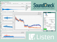
Measuring headphones with digital and noise-canceling circuitry can be tricky. But with careful consideration of more complex and realistic test signals, digital calibration, and careful measurement setup and techniques, it is possible to get meaningful results just like with traditional analog headphones. Users of Listen Inc.’s SoundCheck software can download a free sequence for measuring noise-canceling headphones from Listen Inc.’s website.
Reference
S. Temme and P. Brunet, “A New Method for Measuring Distortion using a Multitone Stimulus and Non-Conherence,” presented at AES 121st Convention, October 2006.
By Brian Fallon, Listen, Inc.
Article originally published in Voice Coil April 2012