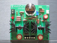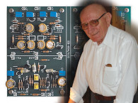
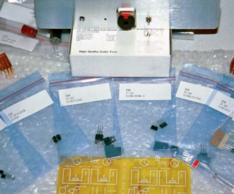
It was time for something better (Photo 1). Rather than going with a new design and engineering model, I wanted a tested, proven, discrete Class A circuit. Several friends suggested Erno Borbely’s MOSFET amp, and with the variety of ways you can buy the PCB and components, it was the best option. With the EB-602/210T design, you can buy just the PCB, the PCB with all components, or the PCB with semis only (Photo 2). I recommend the latter because some of the FETs may be hard to source, and the matching (if needed) is done for you.
The rest was provided from surplus and recycled gear, but there will be more on that later. I will admit I had never heard a pure Class A HP amp. The sound for such a simple and elegant design is better than much more expensive “high-end” systems I have auditioned. This circuit has good detail, dynamics, and low-level resolution. However, I did hear differences depending on the power supply used.

Pure Class
I want to thank Erno Borbely for his assistance, permission to reprint his designs, and for his contributions. The EB-602/210 is a single-ended pure Class A amp capable of driving headphones between 32 and 600Ω. It consists of two identical but separate amps laid out on the same PCB.
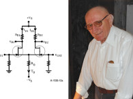
The EB-602/210 requires regulated ±15V to 24V power, and separate supplies are recommended. The schematic (Fig. 1) is the same as Erno’s hybrid tube/MOSFET line amp, published in Glass Audio 1/98. However, the dual triode at the input is replaced by a dual JFET (SK389). The JFET offers less noise, more gain, and better linearity than the ECC86 tube.
It operates as a differential amplifier with about 2mA in each JFET and is supplied by the constant-current diode D1, which is made up of two J508 2.4mA diodes in parallel (or a single J511-4.7mA diode). Q2, D2 comprise a current mirror which converts the out-of-phase signals from the Q1 drains to a single ended signal. Q3 is a 2SJ79 P-channel MOSFET (TO-220) used in common source mode as a Class A output stage.
Its drain resistor, replaced by a second constant-current source, supplies 160mA, thus increasing gain and linearity of the second stage, which is made up of Q4 and associated parts. Q4 is an N-channel MOSFET (2SK216) in a TO-220 package. Open loop gain of the amp is 67dB.
As used in this project, with ±12.5V, Erno suggested I start with the same resistor values as the 15V version, so that I get 160mA for the constant-current source. The resultant maximum power into load is:
300Ω: 200mW
100Ω: 462mW
50Ω: 300mW
32Ω: 219mW
I have tried many types and various impedance headphones from 30Ω to over 300Ω. These include SONY MDR-777 PRO (70Ω), Sennheiser HD570 (62Ω), and some inexpensive 30Ω and 300Ω cans with no sign of clipping and plenty of volume on the amp’s attenuator.

Building the Amp
Construction of the HP amp itself was simple because of the clear documentation sent with it, so I won’t spend a lot of
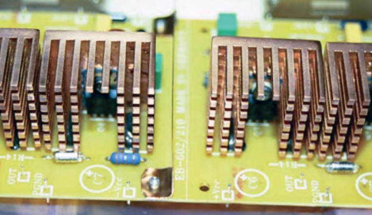
time on PCB stuffing. Specific problems I ran into had more to do with my own additions and modifications. Heatsinks were included but were 1/4” too tall for my case. In Photos 3 and 4 you can see the copper heatsinks originally made for a microprocessor. These had to be cut and machined to fit a TO-220 device perfectly flat, then supported on the PCB with high temp RTV. These keep the temperature close to 48°C on the device. At 12V, R13 = 3R99Ω and R10 = 7R52Ω.
I determined R13 by measuring the voltage (approximately 650mV) across it, and selecting a value slightly above or below 15V values until the current source for Q3 came up to 162mA. Be careful when mounting the MOSFETs to the heatsinks. Use the insulating washers and sil pads provided. Mount MOSFETs on the heatsink first, then solder them to the PCB only after installing all other parts (except C3, C4). Then you can mount C3 and C4. Use proper static handling methods for the semis and check polarity on all electrolytics. I used polypropylene caps, but Dale RN60 resistors work well except where I installed Caddock MK-132 on the input (R1) and output (R14) where some differences could be heard.
I also used a small amount of Teflon solid core silver wire for all audio connections (Photo 4). Short runs and spacing between the wires negated any need for shielded cable inside. I used a copper divider between the channels for all audio grounds (star Gnd), and to keep crosstalk down.
A Case for Recycling
Having made a pattern from the PCB stuffing guide, I used it to mark the amp case for drilling standoff holes. While you can get cases from Audiokits.com for both the HP amp and PSU, I recycled an old 16-bit DAC case after no success selling it. I replaced it with a 24-bit TPC DAC-3.
The power supply case was an old server switch-mode supply with a bad HV transformer purchased from a computer recycler. The DAC case had a black anodized finish on the front plate and was fairly beat up, so I removed all of it down to aluminum with a belt sander with a medium grit belt. By keeping the sander in line (horizontal), I was able to produce a nice brushed look in that direction (edges too). I then used a finer grit sanding sponge (keeping the same direction) until I achieved a smooth-to-the-touch brushed finish (Photo 5).
I first drilled the vent holes in the corners, then cut them with a sawzall. Smoothing the corners with a Dremel and touching up on the edges with black model paint completed the vent openings. I drilled out all holes in panels with a Greenlee stepper bit or Unibit. This is the only way to do holes up to 3/4” diameter for up to 1/4” thicknesses. I mounted the DACT 10K attenuator, Neutrik jack, RCAs, and XLR for power with the unibit.
Chokes and Copper Shielding
In a modern environment where so many sources exist for producing and emitting RF and EMI, you must take them into account and control them. Using batteries is a good place to start, but eliminating the AC connection is not going to stop EMI caused by wireless telecom, HV lines, home wiring, and switching supplies in your computer, to name only a few. RF guys have known this for decades, which is why companies such as Raytheon and Toyota build huge RF anechoic chambers for controlled tests. I was impressed with how well RF screen rooms (copper mesh on a frame around an RF design lab) keep out much of this radiation, so I decided to apply the same principles to this project.
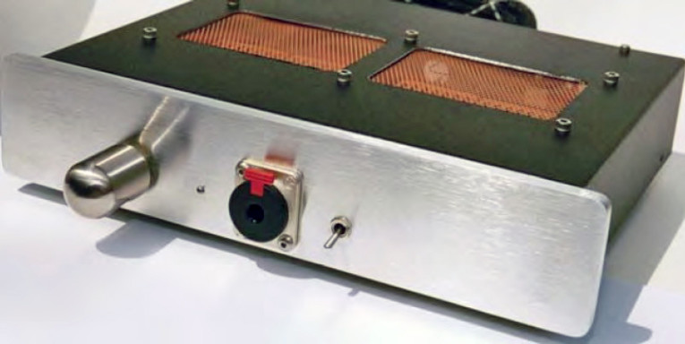
Since you can’t build an anechoic chamber in your homes, use shielding. Pure copper mesh and screen is one way to shield the amp, and can be found in arts and crafts stores. I used Scotch spray adhesive #77 to attach the mesh to the chassis (Photo 4), and several screws with washers to ensure good electrical contact.
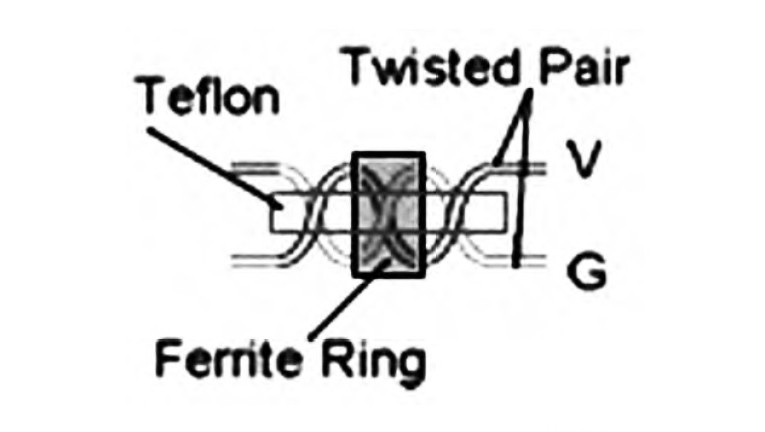
Over the vents I used copper screen (Photo 5) doubled over for strength, and attached with socket cap screws in six locations. Be careful with both types of shielding, making sure no small threads or parts of the mesh touch the PCB, connectors, or short any part of the amp. The two small chokes on the power coming into the amp are simple common-mode chokes (Fig. 2). You can make a simple version by twisting +V and Gnd, −V and Gnd, and slipping a ferrite ring over each twisted pair. These, with the shielding, will help keep RF and EMI at bay. This may all be overkill, but a battery alone is not the end-all solution to power-supply ills.
Power Supply Charger
I chose to go with a battery PSU, but Erno makes a good discrete regulated AC supply, and Audiokits.com has a nice case that it will fit in. For the battery PS, I purchased some new surplus Panasonic 12V 4.5ah lead acid cells, and the intelligent 12V charger (Optimate-Photo 6).
If you decide to build your own charger, I recommend one based on an hysteretic algorithm. These work well, won’t overcharge, and will extend the life of your batteries. I don’t have room to go into chargers here, but many sites exist, and an article in Nuts & Volts April ’03 has a good charger design. Altex.com carries Optimate chargers and batteries. I considered building a charger, but cost was more than the Optimate.
Battery Power Supply
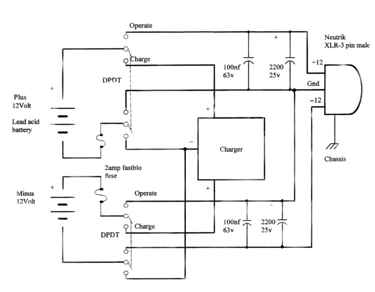
CAUTION: Lead acid batteries can explode if connected in parallel, or shorted, so they must be fused (Fig. 3). I derived the power-supply requirements by taking the total current drawn by the load (each channel draws about 400mA, 2 × 400 = 800mA). Maximum current draw is less than 1A. Realistically, 1.2ah batteries should work, but you should charge them every (approximately) eight hours if you want the full voltage driving your amp (ideal for audio). Alternately, a 2.2ah would be the best choice, needing a charge every 16 hours (worst case).
Since I already had the 4.5ah cells, I figured they would do fine. While a battery’s DC resistance is low, its impedance is relatively high, and more so at high frequencies. For a battery to deliver full energy for short high-frequency energy bursts, you need to parallel it with an electrolytic bypassed with a polyproylene, or polystyrene film cap. A rule of thumb for this is 1000μF per amp of load current. I double that for audio, which gives me about 2200μF (Fig. 3).
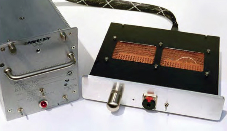
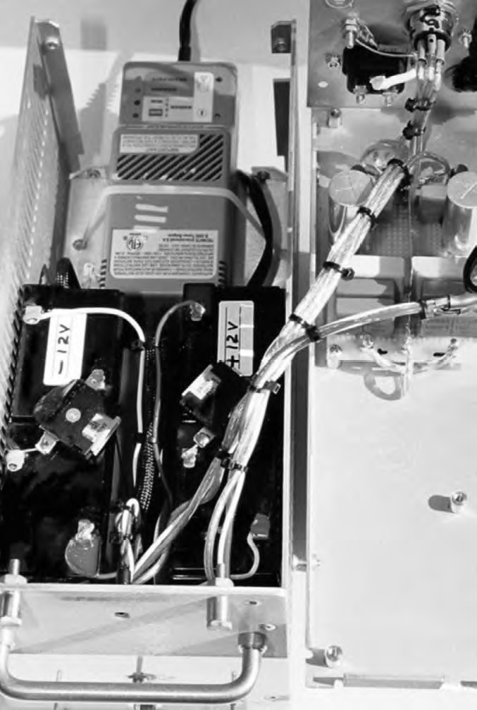
In this PSU (Photo 6), I actually used several WIMA 1μF caps, and one 100nF polystyrene across the 2200μF mounted on a proto-board. PSU (Fig. 3) shows only one 100nF, which is adequate. By removing the battery’s burden, heating is also reduced, thus extending battery life. Automotive fuses (2A) are used to protect the batteries from being shorted together. One battery is charged at a time, but you could build a dual charger to simultaneously charge both. Take note of the polarity of the batteries; −12V polarity is reversed in the Operate switch position (+ to Gnd), but is the same as +12V in the Charge position.
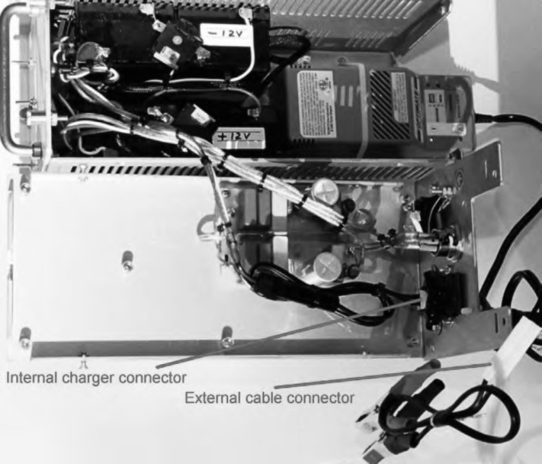
As an option, a connector is mounted on the back of the PSU, allowing external cables to be connected to the charger (Photo 7). Other batteries including car and mower batteries can be charged with a flip of the power switch on the PSU front panel. The DPDT switches are of the ON-OFF-ON type, so left in the center position (OFF) the batteries disconnect (draw no current), and the external charger cables can be used.
Pulling it All Together
After verifying voltages out of the PSU and HP amp bias current (162mA) through R13, I adjusted out any DC offset (P1) using a bench PS and a millivolt meter. Per the instructions, I checked for oscillations, and verified output gain using an HP 206A sine wave generator and a TEK 465B scope.
At 1V RMS the THD measured 0.005% with a 50Ω load, which agrees with published specs. Because XLR connectors were used, I was able to use a microphone cable initially as a power umbilical. With no input, and the volume at full, I noticed a slight hum most likely AC from house wires picked up by the microphone cable, or a ground loop.
To correct this, I made a 5′ 3″ conductor cable and used a separate outer shield (1/4” copper braid sleeve) and connected this to chassis GND on both ends. The Neutrik XLR has a separate connection for chassis GND, and needs to make good contact to the mounting hole. The three wires are connected to +12V, −12V, and PS Gnd. This completely eliminated any hum, and was now so quiet, with volume at full, I needed to check several times to verify it was on. It was on, and now with the DAC 3 as an input fed by a Mitsubishi DD-5000 DVD player and a GW labs DSP upsampler, I could finally hear the result.
After a two-day break-in, the sound was very involving with jazz such as Weather Report, or classical (Debussy’s Clare de’Lune) in which the piano sounded alive without harsh overtones (as it does on other amps), and DVD movies (“Stargate,” “Jurassic Park”). It was a revelation. I was hearing such details as the plucking of the string bass and the drummer quietly setting down a pair of drumsticks midpassage. I had never noticed these with any other HP amp or speaker. Using it now for mixing, composing, and editing, my ears don’t fatigue as quickly, and I get more done.
When I used an AC regulated supply (Linear Tech. LT317), the sound became harder, with more edge, and lost some of the smoothness in the high frequencies. Low end was always very tight and extended with both supplies. I must conclude that the battery PSU makes an audible difference and was well worth the time and cost. Final touches on the amp included a Neutrik HP jack with silver-plated contacts, and the locking mechanism that
keeps me from pulling out the plug. I prefer a stepped attenuator over a pot, and the DACT 10k is reasonably priced.
I also wanted a knob that wasn’t too large, and found a solid stainless-steel one made for cabinets at Home Depot Expo for a few dollars. I had to drill and tap it, but it feels great and is just the right size for this amp. Thanks to Ed Dell and his inspiring editorial on making aesthetics a crucial part of any project, this old 16-bit DAC never looked, or sounded, better.
SOURCES
(the original article mentions Borbelyaudio.com and Audiokits.com websites, which are no longer active)
Alternatives for chassis and parts can be found at diyaudiostore.com and www.parts-express.com
Percyaudio.com Components, braided sleeve, Caddock resistors, MUSE caps, silver wire, extensive audio parts
Altex.com Batteries, chargers, electronics, computer parts
Mouser.com Components, Neutrik jacks and XLR connectors, RCA jacks, more
bgmicro.com Surplus heatsinks, batteries, surplus parts, much more
DIYHIFISupply.com DACT attenuators, audio components, Kiwame resistors, kits
This article was originally published in audioXpress, July 2004.
About The Author
Rick MacDonald, after 15 years as an engineering tech designing and prototyping broadband RF antennae and GPS satellite subsystems, moved into software engineering with E-Systems/Raytheon. Rick’s most recent work has been with digital audio, composing music with MIDI and editing audio for games, software, kiosks, and websites for Gateway, Tandy, and Voyetra, among others. Rick has also written articles for Recording magazine, and has published several books on interactive audio and computer music. He continues to pursue the perfect power supply for all his audio projects.