We think it was time to make it openly available directly here (no more need to search for shady PDFs on the Internet...). To illustrate this post we even selected a build effort from Denmark (theslowdiyer), which includes some nice tips and alternative component choices, complete with additional useful project files. If anyone else has alternative builds, please let us know. We are also interested to know of any companies making the original EB-804/421 kit available today, since Erno's originally website and webshop is no longer available. The aX team.
In the 1/98 issue of Glass Audio, I wrote about a hybrid tube/MOSFET line amp, which, because of its musical sound, became a very popular amplifier (“Low-Voltage Tube/MOSFET Line Amp"). DIY amateurs wished to use it in many different applications, such as CD buffer, I/V converter, power amplifier, and headphone amplifier. It worked very well in all line-level applications, but the second stage was not laid out for high-current operation, so driving headphones was not possible. I have therefore redesigned the circuit to allow high-current operation.
The result is the EB-804/421, a single-ended (SE) pure Class-A amplifier, capable of driving headphones between 32 and 600Ω. The amplifiers need ±15 to ±24V regulated supplies at 160/100mA and 6.3V DC at 300mA for the tube heater. I recommend feeding the amps from separate supplies. The PCB for one amp is 90 × 80mm.
Circuit Description
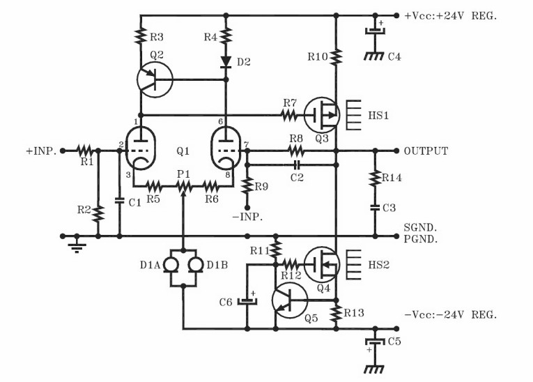
The schematic is shown in Fig. 1. The topology is the same as the hybrid tube/MOSFET line amp. Q1 is a double triode that operates as a differential amplifier, with approximately 2mA in each of the triodes. A constant-current diode D1, which supplies the source current to the differential amp, includes two J508 or E-202 diodes in parallel.
You can also use a single J511, which delivers 4.7mA. The two anodes, which produce out-of-phase signals, are converted to a single-ended signal using a current mirror composed of Q2, D2, and resistors R3/R4. Q3, a P-channel MOSFET in TO-220 package, is used in common-source mode as a Class-A single-ended second stage. I replaced its drain resistor with a second constant-current source, supplying the Class-A current of 100 or 160mA.
The constant current source, which increases the gain and improves the linearity of the second stage, is made up of Q4, an N-channel MOSFET in TO-220 package, and its associated components. I used the Hitachi 2SJ79 and 2SK216 for Q3 and Q4, respectively. You can also use the Toshiba 2SJ313 and 2SK2013, but note that the pinout is different from the Hitachi (GDS versus GSD).
The amplifier can work with a ±15V to ±24V supply. The maximum dissipation allowed for Q3 and Q4 is 2.4W each, so the supply voltage determines the maximum current. At ±24V the current is 100mA and at ±15V it is 160mA. Resistor R13 sets the current: it is 6R8 for 100mA and 3R9 for 160mA. You must heatsink Q3 and Q4. I am using the SK76−37.5 with 8K/W thermal resistance. The temperature on the heatsinks is about 55° C, so proper ventilation is absolutely necessary! The PS/regulator I recommend for the hybrid tube/MOSFET headphone amplifier is the EB-802/243.
The input tube requires a 6.3V/350mA heater supply. Use a well-regulated/low-ripple supply for this (EB-793/204 is recommended). I recommend that you ground the negative side of the heater supply to the PGND on the PCB.
Linearity Notes
The input tube dominates the overall distortion characteristics of the amplifier. Tubes of different manufacturers produce different amounts of distortion. I have tested the ECC86 from Telefunken and Ultron, ECC88 from AEG, E88CC from Tungsram, and 6922/6H23Π, a Russian military tube. All worked fine, but the difference in THD can be 6 to 10dB!
The Russian 6922/6H23Π produced the lowest THD. We are shipping the kits with these tubes. Nevertheless, I recommend that you try different types of tubes and select the one you like best.
Note also that the tube can pick up hum from mains fields. Again, tubes from different manufacturers show different sensitivity to these fields. It would help to use a shielded tube socket; however, it is difficult to find one for PCB mounting.
Finally, it is a good idea to switch on the heater before you apply the ± supply to the amplifier. This has nothing to do with cathode stripping, but with the DC operation of the amplifier. As long as the heater is off, the input does not function even if you apply the ± supply. Consequently, the DC feedback loop is inactive and the output is not sitting at 0V.
Only after the heater is on can the output stabilize to 0V. Alternatively, you can leave the heater on all the time or in a stand-by mode with say 4V, in which case you can apply the full heater voltage and the supply voltage simultaneously.
The feedback resistors R8 and R9 set the closed loop (CL) gain of the amp. Normal gain is 10×, or 20dB. Changing R9 can change this gain. CL output impedance is 15Ω. Equivalent input noise depends on the tube used and is 1.2 to 1.5μV!
The maximum output power into different loads depends on the supply voltage and the available current from Q4. With ±24V and 100mA in the second stage, the amp delivers >100mW into 32Ω and >250mW into 600Ω at 1% THD. With ±15V and 160mA the power into 32Ω increases to 300mW at 1% THD.
The maximum power is limited by the available current at low load impedances and by the available voltage swing at high impedances. If your headphones are low impedance, you should operate the amplifier at ±15V with 160mA in the second stage, and if they are high impedance, use a ±24V supply with 100mA. Since high impedance headphones require less power than the low impedance ones, the ±15V operation will probably give more than enough power for ear-shattering SPL over the whole impedance range.

Assembly
Figure 2 shows the stuffing guide for the hybrid tube/MOSFET headphone amplifier. Start the assembly by installing the solder pins, jumpers, and then all the resistors (including the trimpot P1). If you have selected ±15V operation, then resistor R13 = 3R9 and R10 = 7R5.
If the supply voltage is ±24V, then R13 = 6R8 and R10 = 33R.
Next install Q2, Q5 and diodes D1 (A/B). Mount Q3 and Q4 on the heatsinks with insulator and install them on the board. Make sure the MOSFETs are properly tightened to the heatsink. Then install the tube socket and all the capacitors, with C4 and C5 being the last ones. Finally, plug the tube into the socket.

If possible, test each amplifier separately before installing it in the chassis. This simplifies measurements, adjustments, and, if necessary, component changes. If you have access to a scope, connect it to the output of the amp and check whether radio frequency (RF) oscillations are present. If you have a complete audio instrumentation in your workshop, perform the usual gain, frequency response, noise, total harmonic distortion (THD), and intermodulation distortion (IM) measurements.
Connect the +INP and the −INP to SGND. Apply the appropriate supply voltage (±15V or ±24V) and the 6.3V DC heater voltage to the amplifier. Connect a digital voltmeter (DVM) across R13 and check the voltage drop. It should be 0.62−0.65V. This sets the current to approximately 100mA or 160mA in the second stage, depending on the value of R13.
Let the amp run for about 20 minutes before you adjust the offset. Connect the DVM to the output of the amplifier and set the offset voltage to 0V with P1. This completes the DC adjustments. aX

Click on the image for the link.
This article was originally published in audioXpress, April 2005
| EB-804/421 | |
| Resistors, Trimpot | |
| R1,R7,R12 | 100R |
| R2 | 1MEG |
| R3,R4 | 499R |
| R5,R6 | 47R5 |
| R8 10k | RN60 |
| R9 1k1 | RN60 |
| R10 33R | RN60 (±24V) |
| 7R5 | RN60 (±15V) |
| R11 | 10k |
| R13 6R8 | RN60 (±24V) |
| 3R9 | RN60 (±15V) |
| R14 | 47R5 |
| P1 | 100R Copal |
| All resistors non-magnetic Dale CMF 135 and RN 60 | |
| Capacitors | |
| C1 100pF | 160V PS |
| (Optional) | |
| C2 10pF | 160V PS |
| C3 1000pF | 160V PS |
| C4,C5 220μF | 35V |
| C6 100μF | 25V ROE EKO |
| Tube, Semiconductors | |
| Q1 | ECC86/6GM8, ECC88/6DJ8, E88CC/6922, 6H23Π-EB |
| Q2 | 2SA872 |
| Q3 | 2SJ79 INS. |
| Q4 | 2SK216 INS. |
| Q5 | 2SC1775 |
| D1 | J508 or E-202 (two in parallel) |
| D2 | 1N4148 |
| Miscellaneous | |
| PCB EB-804/421 | |
| HS1,HS2 SK76-37.5 | |
| 12 × 1mm solder pins | |
| 4 × M3 screws, nuts | |
| 2 × 9-pin PCB tube socket | |
| Mounting hardware | |