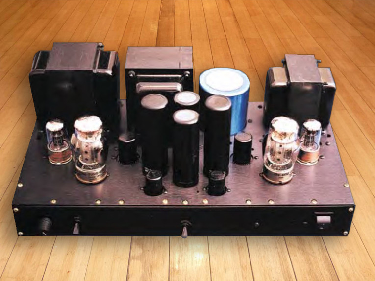
You will see here that the 6550 can also be used in a clean, sweet-sounding, single-ended design. The amplifier has very few parts, is easy to build and repair, and the cost of the project is nominal when you consider the kind of sound that is produced. The transformers used in this project are available from a couple of sources; the brands of tubes you use are, of course, your choice.
I chose transformers from Hammond, which makes a great single-ended output transformer — the 1628SE — that was perfect for this amplifier. See the parts list in Table 1. The power transformer Hammond manufactures, the 270HX, supplies all the voltages needed for the power supply. Antique Electronic Supply (AES) stocks Hammond products, including chokes, and is very pleasant and professional to deal with.
AES is also one of the few suppliers to carry my most favorite of all the 6550s ever made — Tung Sol. This wonderful beam-pentode power-amplifier tube has a sound unmatched by all the others, regardless of their ad claims. I used these when I built the 70W Mac project that Bruce Rozenblit contributed to the GA 1/90 issue. I tried other brands at first, but it wasn’t until I put in the Tung Sol tubes that the amp really came alive.
I’ve been hooked on the sound of these tubes ever since, and have searched high and low to find more of them. They cost more than the other brands, but if you can find them, please give them a try — you won’t regret it. The highs are very smooth and clean, the mid-range has magic, and the bass is more solid and articulate than I’ve ever experienced with any other type or brand of power tube.
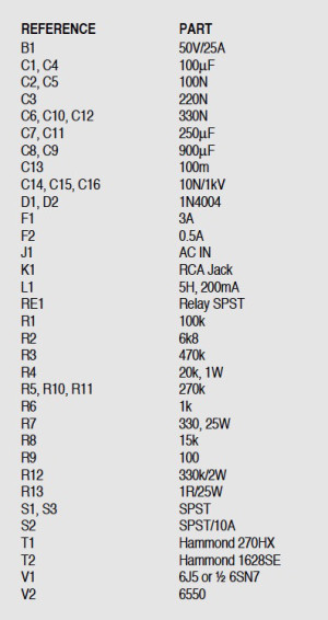
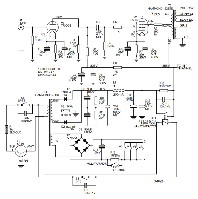
This article will contain no complex math or equations, but only the basic information you will need to complete the amp. The circuit is very straightforward and should not give you any problems if you follow the schematic diagram (Fig. 1). (Note: The diagram shows the pinout for the 6J5, not the 6SN7.) Tube V1 is a 6J5 triode, actually one half of a 6SN7, so if you wish to save on space and cost, you can use a 6SN7 and just wire in each triode section to the proper channel. I used the 6J5 because it improved the looks of the completed amp and because the chassis I used had plenty of spare holes. I obtained the 6J5s from AES and they are the Raytheon brand, a beautiful tube with one triode section standing alone in the center of the glass envelope.
I also purchased the Tung Sol 6550s from AES. According to the factory specs, the 6550 in single-ended mode is capable of a fairly good power output. The spec sheet shows almost 20W of Class A1 output for a single tube, with a plate voltage of 400V and G2 voltage at 225V. The output on this amp is probably a little lower, but it certainly doesn’t sound like it. When it’s driven by my VTL PR-1 preamp, I can’t move the volume control
past the 10 o’clock position without nearly being driven from the room!
Hammond includes a 40% tap in the primary winding of its 1628SE transformer. This is left unused if you wish to try the amp in the triode mode, with a 120Ω 5W resistor tying G2 to the plate, and with some power reduction, of course. I think the amp sounds great either way. I used Holco resistors in the amp circuit. The power supply uses metalfilm, and the large power resistors are wirewound types from NTE. The coupling capacitors are from MIT, and all the power-supply and cathode caps are bypassed with small-value MITs.
Bypass Caps Work!
I don’t like using electrolytics when they can affect the signal, so I took Eric Barbour’s advice (GA 1/93) and used the bypass caps to help smooth out the high frequency. It works! Because this circuit is so simple, you can experiment with it all you like. You can try a different power supply, transformers, resistors, caps, and any brand of 6550 or KT-88 tube.
For the rectifiers in the B+, I used half of a full-wave bridge I had in stock, rated at 800V and 5A. This made for easy mounting of the rectifiers because this part has its own case, which is also a heatsink. Switch S2 is for soft-starting the heaters, and S3 is to delay the B+ until the cathodes are warmed up to prevent stripping.
You can build the amp without these switches, but I’m going to do all I can to prolong the life of these precious old tubes. The completed amp is quite heavy, so I assembled it with all the parts except for the output transformers, saving them for last. This made moving the chassis around a lot easier and safer. These transformers have their core plates turned at 90° angles to each other.
This amp, like most SE amps, is speaker-sensitive. You should try some different combinations to achieve the results you desire. I found that Focals, at 92dB efficiency, sounded very good, but some Polk speakers, at 90dB, were more open and airy. Over the years, after using many brands and types of speakers, I have found that Legacy produces what I consider to be the king of full-range high-efficiency speakers. I have their Focus model, which sports a 96dB efficiency with a response of 16Hz to 30kHz!
These speakers, when used with tube amplifiers, have the best midrange sound of all that I’ve heard in my 41 years of working with audio systems. They are currently hooked to the Mac 70s, and the amps drive them without even the slightest indication of being overworked. I have even driven them with an old Harman Kardon push pull amp using 6V6s and rated at only 12 to 14W.
Natural Sound
The sound of this amplifier is very full and natural, and the way it treats the female voice is amazing. On Jennifer Warnes’ album, The Hunter, track 2, I felt as though she were almost in the room with me. Enya’s delicate voice has never sounded so beautiful. The same goes for Sade on her album, Stronger Than Pride, track 9, which has a soft and easy sound as she “sighs” the words. If you have any friends who think that tubes can’t handle bass as well as solid state, just play the album The Misty Mood of Three Blind Mice, track 5, and watch their expressions change. This track, and track 8, have over twelve minutes of the best recording I’ve ever heard of string bass notes. (And, yes, if you notice the bass starting in the left channel only, you’re hearing correctly.)
This amplifier has been a great “test bed” for the 6550s that are currently available. With only one tube to change for each sampling and no bias adjustment to worry about, it was very easy to compare tubes. GE’s own 6550A was really good, with great highs and a very open midrange. It would be my second choice after the Tung Sol. The Svetlanas also sound good, have a lot of midbass punch, and are very good from sample to sample.
I’m sure that most readers are aware of the possible higher distortion levels in this SE design versus some PP designs, but that’s not the end for which I build. I build and modify my circuits to suit the ear, not the meter. I’ll “tune” an amp until the sound is pleasing and just right. Using the components I’ve listed has given me that sound. If you use good construction techniques and good parts, you’ll have the same results.
Construction Hints
If you love this hobby as much as I do, then whenever you see a new and different diagram or picture of a piece of audio equipment, you probably can’t help but wonder what it would be like to build your own version of it and see just how well it will work and how good it might sound. In total, I’ve built over 30 projects consisting of preamps, amps, and speakers, and I still feel the same excitement every time I start something new. That’s how I felt when I decided to build something new and different with the 6550s I had on hand.
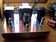
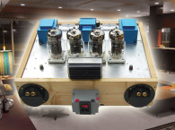
The chassis I chose had what seemed to be a vast expanse of open space for just four tubes, but part of the thrill of being a doityourselfer is working out your own topology and circuit layout and being able to put things exactly where you wish them to be. The chassis, all 18″ of it, had lots of holes to fill, so instead of installing the filter capacitors inside, I opted for above-the-top-plate mounting.
With only the two 6J5s and the two 6550s on such a wide platform, the caps filled in the holes and the extra space quite nicely. If I ever need to replace or upgrade a capacitor in the future, it will be an easy task. These capacitors are mounted on regular project breadboard that is attached to the bottom of the chassis plate.
To make it easier on the old memory cells, I painted the bottom of the plate with flat white enamel and then labeled the terminal strips and other wiring points with a marker pen. This is a big time-saver, especially if I must stop the project for a few days, and it also helps for any future service or repair needs. By the way, I used the two 900μF caps in series because I had them in stock. You can use any good-quality capacitor here that is rated at 450V. Just be sure to have adequate capacitance, and your power supply will probably be really quiet like this one. Also try to use good-quality wire when building this or any other project, and use good soldering technique. I find that type THHN and THW copper wire, which is rated for 600V, is fine for the power supply and heater circuits and is available at almost any hardware store.
For the signal circuit, I try to use Cardas or other Teflon copper or silver wire, but I really can’t tell the difference in sound between one good-quality wire and the others. I truly believe that good sonic performance comes from the resistors, capacitors, transformers, and tubes you use.
Other Handy Tips
The schematic in Fig. 1 should be fairly easy to follow. On the diagram you will notice in the power supply that the 6.3V DC wiring for the tube heaters is connected to allow for equal voltage at all the tubes, instead of having one of them with a slightly lower voltage at the end of the usual wiring “chain.” This technique has always worked well for me, especially when using tubes that pull a lot of amps on their heaters or filaments.
You will also see that the B+ switching relay has a resistor and capacitor across the points. This is to prevent point-flash and to help eliminate the “pop” or “thump” that is always annoying in your speakers when the B+ hits the tubes after the cathodes are warmed up. Please try to power up any new project with a Variac and an amp meter, also available from AES.
I’ve found a digital wattmeter is also great for monitoring the power draw when ramping up the AC voltage. Always try to keep a voltmeter on the 6.3V and the HV in case of any low readings or any overshoot. These readings, when done without the tubes in place, will always be a little high, of course; and don’t forget to safely discharge the filter caps, thus preventing those unpleasant surprises we have all experienced!
I always test the tubes beforehand, even new ones, to make sure they are up to specs. If you finish your project and power up with a bad tube in place, it may send you searching through the entire circuit you had already tested and were pretty sure was OK up to this point. It is also a good idea to check any resistors and capacitors you will be using, to ensure you have a good match in values, and to catch any problems in advance.
This amplifier seemed to require about 25 hours of break-in time, so be patient and allow everything to settle in. What’s the best way to break in your new amplifier? Why, listen to your favorite music, of course! Factory units always need time to break in, and our homemade units are certainly no exception.
This article was originally published in audioXPress, September 2001.