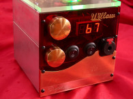
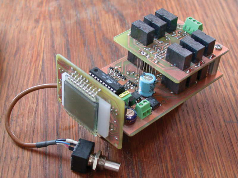
I played with digital pots, but they introduce semiconductors and add impedances into the circuit. They are also limited by how much voltage — both positive and negative — they will accept. I decided to take out a clean sheet of paper and start from scratch to see whether I could make a pot that rivaled present designs while maintaining a reasonable cost. This, then, is the result of that inquiry (Photo 1).
I wanted flexibility — that is, I wanted to be able to use it in audio or any design and I wanted to be able to manipulate the value of the pot with just a few components to simplify other applications. Also, it must have a high degree of accuracy along with its flexibility. Next I wanted it to have as few — if any — moving parts and a long life that didn’t require any maintenance or lubrication. I wanted it to work as well in 10 or more years as it did the day I built it. I also wanted to know what level the pot was at all times so I could return to a specific point or listening level at any time.
The Design
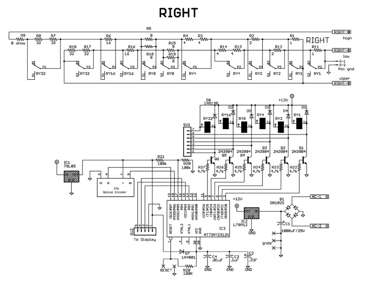
For this design, I used an Atmel ATtiny2313V, 8-bit microcontroller programmed in assembly. It let me control the LCD and the output to the relays and also enabled me to use a small capacitor 0.33 F to save my settings with the power off so my circuit would not draw — nor require — any external power in the off condition.
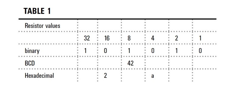
The design uses binary-coded decimal (BCD) to select any level from 0 to 63 by manipulating six double-pole relays (Table 1). This has the advantage of requiring only 12 resistors (although I will be using 18, but more about this later). Of the 18 resistors, only nine are ever in the circuit at any one level, so for stereo I employ 18 resistors total for 64 levels and two channels. BCD is reflected in the program as hexadecimal, so no manipulation of the data is required for the outputs from the registers. Again, you can see this in Table 1.
I chose the relays carefully because current draw, contact isolation, and relay life needed to be examined for the design to work well. The relays draw 6 mA each. For stereo, there are 12 relays, six per channel. You can add channels and have four or more channels simply by building more auxiliary boards. In the same respect, you can have only one channel for monaural or to control a three-terminal regulator in an entirely different application if you desire.
These relays are hermetically sealed, washable, and have gold-plated contacts; their cost is also low — 12 relays cost under $40. The engineers at Tyco who make the relay told me that the mean time between failures (MTBF) is in the millions at the low current and voltages that audio circuits require. Using relays and not MOSFETs or other electronic devices means that you have no positive or negative voltage limitations and the controlled circuit only sees the combinations of resistors.
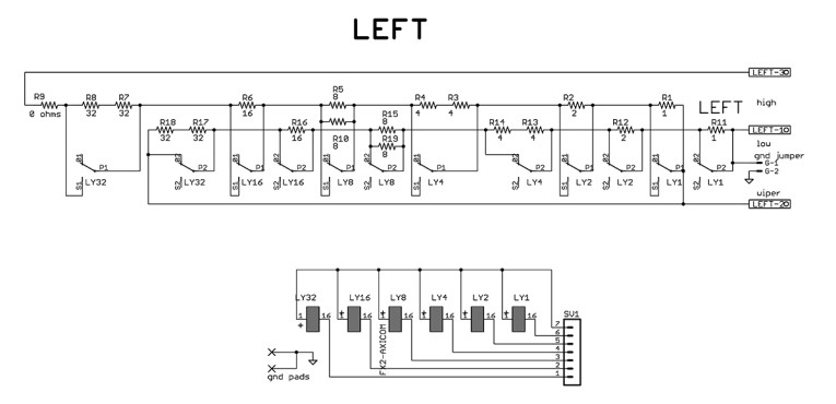
It is also important to realize that nowhere in this circuit is any switch exposed to outside air, thus oxidation is not a factor. For the resistors, I used Panasonic SMD low-noise, 0.1%, 1/8-W metal film devices. With the pot at maximum — 64K in my application — the total resistance error was 6 Ω. At the lowest value (1K), the measured resistance was 1000.13 Ω (four-wire method). To make up the values shown in (Table 1) only requires three resistor values: 1, 2, 16 Ω.
This can be in any multiplication: 10, 20, 160, 10k, 20k, 160k, and so on. For example:
Resistor 1 = 2 Ω (parallel)
Resistor 2 = 2 Ω
Resistor 4 = 2 × 2 Ω (series)
Resistor 8 = 2 × 16 Ω (parallel)
Resistor 16 = 16 Ω
Resistor 32 = 2 × 16 Ω (series)
You can also start the progression with 2: 2, 4, 8, 16, 32, 64, to give you 128 Ω total for 10 resistors using the original two values.
For trouble-free operation, I used a low-cost 64-step optical encoder to switch the relays through the microcontroller. Operating as a stereo volume control, there is no sense of “stepping” as the volume is increased over its 64 steps. The complete process is smooth and detent-free.
It is possible to isolate the relay low clicking noise completely, but it is not overbearing, and I personally enjoy the positive sound as I run up and down with the control. Most times I just change the volume to a new level, and the fact that I’m using a sophisticated control is not an issue. It’s kind of neat, actually! This control, however, is especially suited for the most sophisticated hi-end audio products. I did not add remote control to this design, but the design, by nature, lends itself well to this addition.
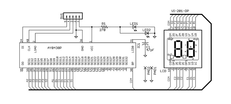
For this project, the ATtiny2313V, along with an AY0438 driver for the display, does all the work. The display mounts on the main board with the power supply. I did not isolate the supply from the resistor boards because noise measurements are below what my instruments can sense. The resistors are not tied into any part of the circuit, only the sealed relay contacts. In my stereo control, I used a jumper to tie the low leg of the pot to ground, but in all respects the resistors are autonomous.
When the power to the BCD pot is off, current draw from the circuit is less than 200 nA, and the 0.33 F capacitor will run for weeks holding the last level before going below 1.8 V—at which level this chip is capable of running. Last, I included the LCD for a relative level: 31 can be 31 Ω or 310 k Ω, I did not see any need to set dB output indications. My thinking is that volume is set to a specific level and what is paramount is knowing and returning to that level. This applies to instrumentation as well.
Software And Operation
The software was written in Atmel’s Studio 4 in assembly. It starts up with an initialization of the registers driving PortD, the relay port; the initial output is “00, ” which is the lowest setting. From there it goes to the LCD and loads the same value as the outputs and sets the load lead hi to lock the value. If no other input pulses come in from the encoder, the microcontroller goes to “wait” for a change in the encoder state and pro-and the LCD.
When the circuit is powered down, pin 17 (PortB,5) low sends the program to sleep (power down mode). In this mode, the internal 4-MHz oscillator turns off and the last output values are saved. Wakeup is from a pin change (PortB,5 again) going high, which sends the program to wait for a change from the encoder (pin 19, PortB,7) and the cycles repeat. The output (PortD) drives the six 2N3904 NPN transistors through the six 4.7k resistors, and the transistors in turn drive the 12-V relays by grounding the negative side (pin 16).
When the power to the circuit is turned off, the 1N4001 diode on pin 20 of the microcontroller isolates the microcontroller and the 0.33-F capacitor from the LCD and the relays. In this configuration, the only power the capacitor sees is that of the microcontroller in sleep mode; on wakeup it is recharged to 4.3 V (5 V minus the 0.7 V loss from the 1N4001 diode). Do not change this diode to a Schottky diode because it has too much leakage, and the voltage drop benefit will not make up for the extra load on the 0.33-F capacitor.
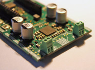
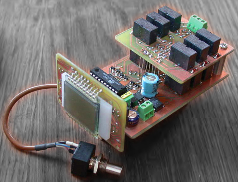
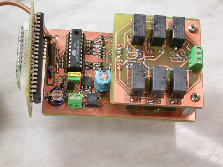
Construction
Building the circuit is straightforward with a mix of SMD and through-hole components (Photo 2). The only components not on the board are the LCD, which attaches with a single five-pin 90° connector, and the encoder. You can connect the LCD with a wire harness extended to a front panel if desired, as you can with the encoder. In my case, I attached the display to the main board and the encoder with wires (there are four).
Build the main board first and test the voltages before inserting the encoder or the microcontroller. Pin 20 of the IC socket should have about 4.3 V and the encoder should be just about 5 V. The positive side of the relay (pin 1) should have 12 V. These are polarized relays, which won’t operate with B+ attached to pin 16. The LCD should also be attached after the initial testing and have 5 V on pin 1. Power for the circuit can be from a 12-V transformer at 300 mA or 15 V DC. This is handy to allow tapping off audio power when used as a stereo pot.
I placed auxiliary relay boards for additional channels on 19-mm (3/4") standoffs and ran wires through the connector to the main circuit. Place the AY0438 driver chip on the underside of the LCD board and the LCD on top. The two SMD LEDs (I used amber) light the display in low light conditions.
I also inserted a piece of milky white Lexan between the LEDs and the bottom of the display to diffuse the light hitting its underside before I soldered it in place. While this is not required, it does add a nice touch. I did not build a dedicated case for this pot because it’s going into my latest audio design. This device will also work nicely in an active audio control along with an input switching circuit plugged into a preamp.
I have placed an adjusting resistor (R9) on the relay boards to help when using the circuit for different applications. With my audio circuit, I simply shorted across R9 to remove it from the circuit, which must either have the resistor or a short in its place.
Conclusion
This design turned out exceptionally well; it works with no glitches and its accuracy is far better than an audio circuit could ever need. I like the fact that it acts as a smooth transition when passing from one level to the next.
I have never understood why detents were ever put into audio pots, especially with many having only 24 specific levels. I always seem to be listening somewhere between two detents, and multiple switch pots are no better. This pot with 64 levels and precision metal film resistors is hard to beat for sound or facility. I hope you enjoy building and utilizing it as much as I enjoyed designing it! aX
Specifications
• Noise: Less than 5 mV
• Linearity better than 0.1%
• Maximum error less than 0.1%
• Current 110 mA peak, two channels
• Main board dimensions: ~5.7 cm W, 9 cm L, 3.8 cm H (two channels)
• Auxiliary boards ~5.7 cm W, 5.7 cm L
About the Author
Robert Nance Dee is a retired electronics engineer. He worked with the first military computers, has several patents, and has written many magazine articles. He enjoys machining, watch making, bicycling, cabinet making, and philosophy. He is an amateur arborist, an environmentalist, and a vegetarian who thinks his life is a hobby. His passion for audio, in every form, spans 50 years and started in high school while working part time in a radio television repair shop. He lives off the grid in a house he built surrounded by animals and fruit trees in the Catskill Mountains. His audio projects are named after his animals and friends.
This article was originally published in audioXpress, September 2011.