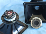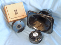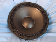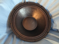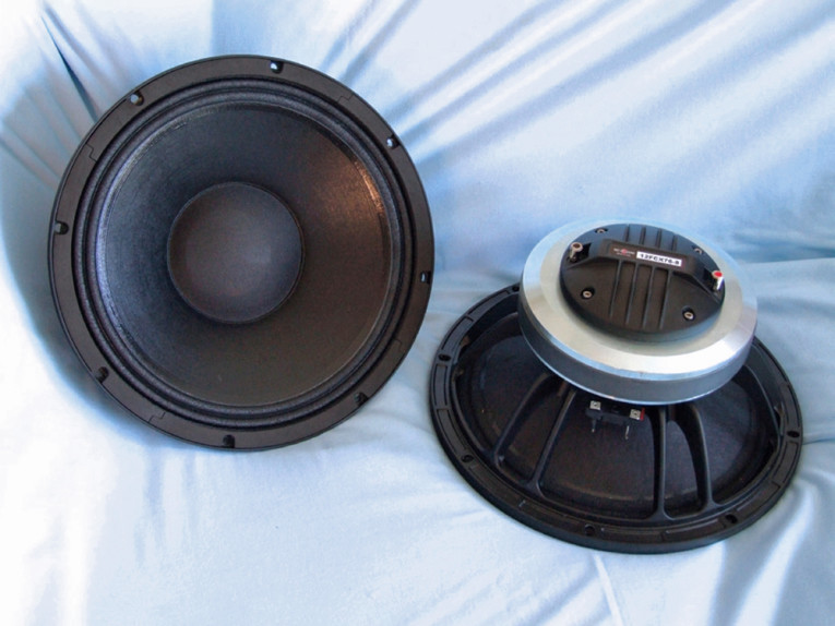


The 12FCX76 uses ferrite motors for both the woofer and the compression driver. In terms of features, the 12FCX76 woofer is built on a 12-spoke (six twin-leg spokes) cast aluminum frame with eight mounting holes (see Photo 1). For cooling, there are 12 2-mm × 15-mm vents between the back of the frame and the motor front plate that open into the plate area and provide an air path across the front plate and voice coil.
The woofer ferrite motor structure — with the compression driver attached to the woofer back plate — is attached to the frame and fires into what would normally be a pole vent. The woofer motor utilizes a 21-mm × 190-mm ceramic magnet sandwiched between a polished and shaped front plate and polished and shaped back plate. A short 70-mm diameter conical aluminum horn attached to the top of the pole piece completes the compression driver. This is covered and concealed by a 4.5” diameter breathable dust cap.
Visible motor parts for the compression driver include the shaped rear diaphragm cover with eight heatsink fins. As with most B&C Speakers compression drivers, the diaphragm is field-replaceable (see Photo 2). The 12FCX76 woofer cone assembly includes a curvilinear front-coated paper cone suspended by a coated-cloth M-shaped surround. A 76-mm (3”) diameter voice coil wound with copper wire on a nonconducting former terminated to a solderable terminal block couples the cone to the driver motor. For the high-frequency compression driver, B&C Speakers incorporates a titanium diaphragm coupled to a 75-mm (3”) voice coil wound with aluminum wire.
I used the LinearX LMS and VIBox to produce both voltage and admittance (current) curves with the 12FCX76 clamped to a rigid test fixture in free air at 1, 3, 6, 10, 20, and 30 V. Note that the LMS oscillator is turned on for a progressively increasing time period between sweeps to keep the driver heated as close to the third thermal time constant as possible (from 10 to 30 s between sweeps, depending on the voltage level). Following the established Test Bench test protocol, I no longer use a single added mass measurement. Instead, I used an actual measured cone assembly weight provided by B&C Speakers. The 12FCX76’s woofer motor stayed fairly linear throughout the test sequence and none of the curves were discarded.
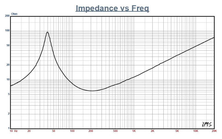
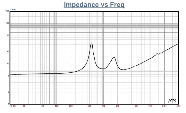
Next, I post-processed the 12 550-point stepped sine wave sweeps for each sample and divided the voltage curves by the current curves to derive impedance curves that were phase calculated. I imported them along with the accompanying voltage curves to the LEAP 5 Enclosure Shop software. Because most T-S parameter data provided by OEMs is produced using either a standard model or the LEAP 4 TSL model, I also used the 1-V free-air curves to create a LEAP 4 TSL model. I selected the complete data set, the LTD model’s multiple voltage impedance curves, and the TSL model’s 1-V impedance curves in the transducer derivation menu in LEAP 5 and created the parameters for the computer box simulations. Figure 1 shows the 12FCX76 woofer’s 1-V free-air impedance curve. Figure 2 shows the 12FCX76 compression driver’s impedance curve.
Table 1 compares the LEAP 5 LTD and TSL data and factory parameters for both 12FCX76 samples. The 12FCX76’s parameter measurement results were reasonably close to the factory data except for some deviation in the VAS. Given that, I used the LEAP LTD parameters for Sample 1 to set up computer two enclosure simulations. This included two vented alignments, a QB3 alignment and an extended bass shelf (EBS). This resulted in a 2.25 ft3 QB3 box with 15% fiberglass fill material tuned to 51 Hz for the QB3, and a 2.5 ft3 box for the EBS-vented alignment tuned to 40 Hz, also with 15% fiberglass fill material.
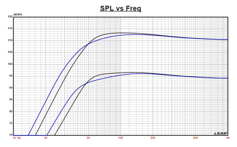
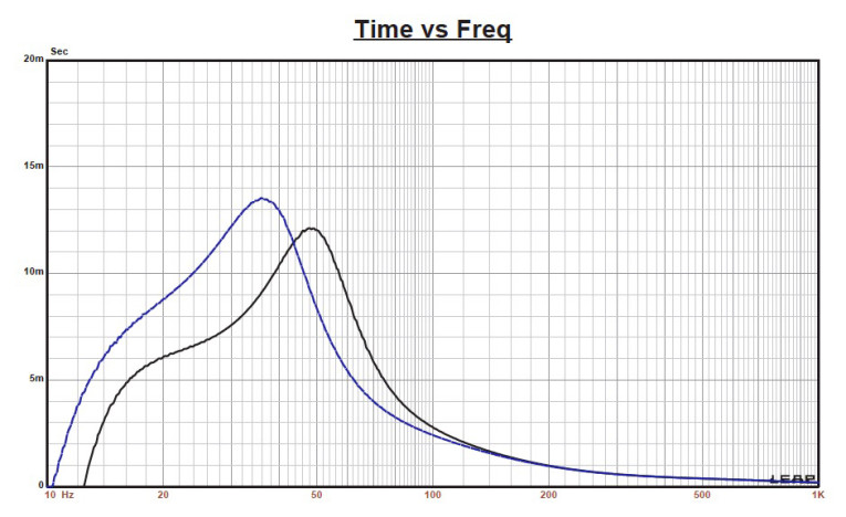
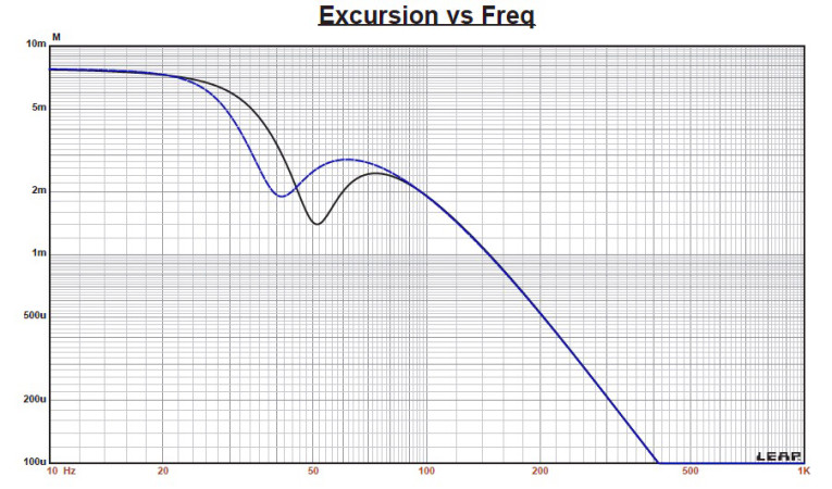
Figure 3 shows the 12FCX76 woofer’s results in the two vented boxes at 2.83 V and at a voltage level high enough to increase cone excursion to 7.5 mm (XMAX + 15%). This produced a F3 frequency of 751.8 Hz (–6 dB = 44.9 Hz) for the 2.25 ft3 box tuned to 51 Hz and –3 dB = 55 Hz (–6 dB = 40.6 Hz) for the 2.5 ft3 box EBS-vented simulation tuned to 40 Hz. I increased the voltage input to the simulations until the maximum linear cone excursion (XMAX + 15%) resulted in 113.5 dB at 20 V for the QB3 enclosure simulation and 112.5 dB at the same 20-V input. Figure 4 and Figure 5 show the 2.83-V group delay curves and the 20-V excursion curves.

Klippel analysis for the 12FCX76 produced the Bl(X), KMS(X) and Bl and KMS symmetry range plots are shown in Figures 6–9. Our analyzer is provided courtesy of Klippel and Pat Turnmire of Redrock Acoustics performed the analysis. This data is valuable for transducer engineering, so if you don’t own a Klippel analyzer, Redrock Acoustics can provide Klippel analysis (www.redrockacoustics.com).
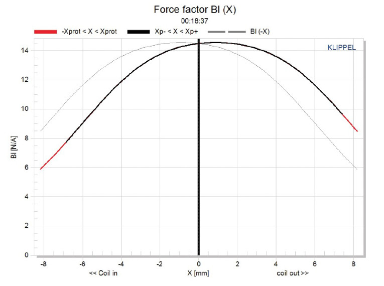
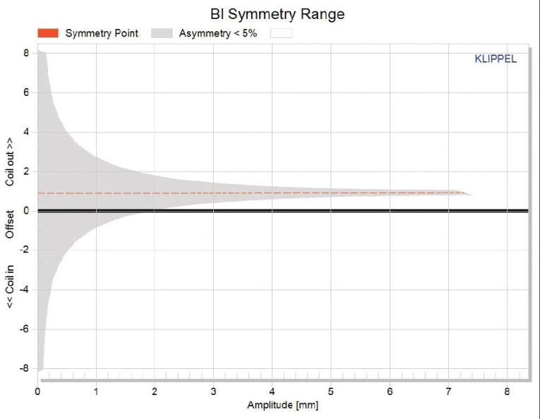
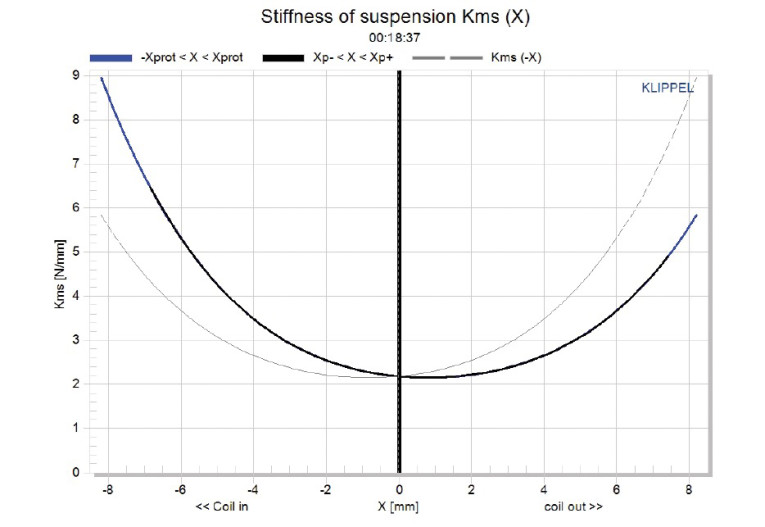
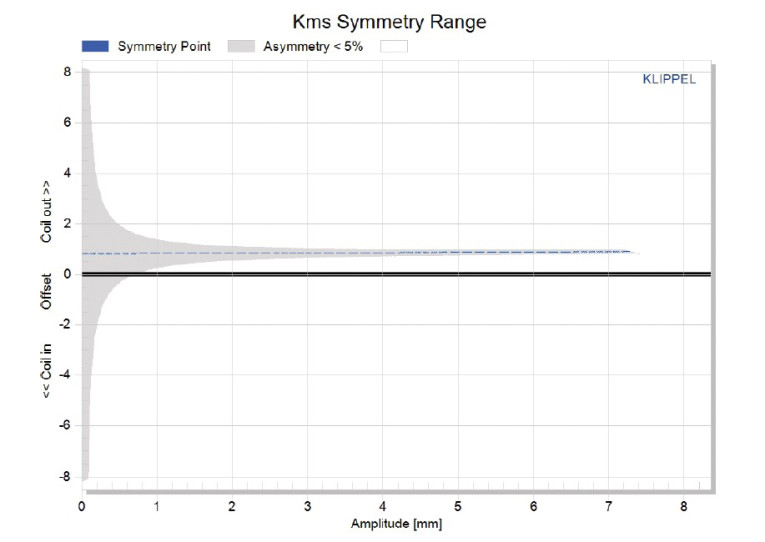
Figure 6 shows the 12FCX76 woofer’s Bl(X) curve, which is moderately broad and mostly symmetrical with some offset. Figure 7 shows the Bl symmetry plot, which has a small 0.88-mm forward (coil-out) at the rest position and only increases to 0.91 mm at the driver’s physical XMAX, suggesting the 12FCX76’s compression driver is slightly out from magnetic center but probably within QC tolerance. Figure 8 and Figure 9 show the 12FCX76’s KMS(X) and KMS symmetry range curves. The KMS(X) curve is also quite symmetrical in both directions, with a small amount of coil-out (forward) offset. Looking at the KMS symmetry curve, the offset is 0.88 mm at the zero rest position, and only increases to 0.92 mm at the physical XMAX, staying more or less constant throughout its operating range.
The 12FCX76’s displacement-limiting numbers calculated by the Klippel analyzer showed the XBl at 82% (Bl decreasing to 82% of its maximum value) was 4 mm and the crossover (XC) at 75% (compliance decreasing to 75% of its maximum value) was 2.9 mm, which means the 12FCX76’s compliance is the most limiting factor at the 10% prescribed distortion level. That 10% may be conservative given the relative difficulty of subjectively perceiving total harmonic distortion (THD). So, if we apply
the 20% distortion criteria with Bl decreasing to 70% and compliance decreasing to 50%, then XBl = 5.3 mm and XC = 5.1 mm.
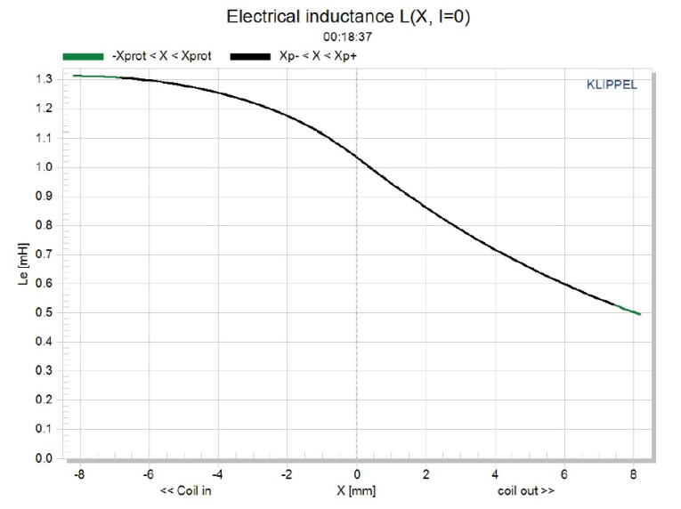
Figure 10 shows the 12FCX76 woofer’s inductance curve L(X). Inductance will typically increase in the rear direction from the zero rest position as the voice coil covers more pole area unless the driver incorporates a shorting ring. Since the 12FCX76 does not incorporate a Faraday shield (shorting ring) in the motor assemble, we see the typical inductance rise for the coil-in direction of motion.
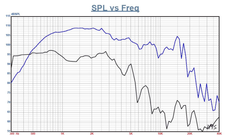
However from XMAXIN to XMAXOUT, the inductive change is fairly small at between 0.33 to 0.55 mH. I mounted the 12FCX76 in an enclosure that had a 15” × 16” baffle and was filled with damping material (foam). Then I measured the woofer’s and the compression driver/horn’s on- and off-axis frequency response from 300 Hz to 40 kHz at 2.83 V/1 m (100-point LMS gated sine wave sweep). Figure 11 shows the 12FHX76 woofer’s on-axis response along with the compression driver/horn’s on-axis response. The 12FCX76 woofer’s response has a smooth rising response to 800 Hz followed by a 6-dB breakup peak at 5 kHz, just prior to the low-pass rolloff.
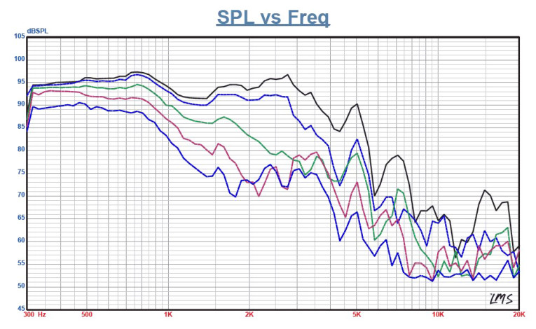
For the 12FCX76 compression driver/horn, the response is ±1.5 dB from 800 Hz to 3 kHz, followed by a declining response out to 20 kHz. Figure 12 shows the 12FCX76 woofer’s on- and off-axis frequency response at 0°, 15°, 30°, 45°, and 60°. At –3 dB at 30°, the on-axis curve occurs at 1 kHz , which makes 1 to 1.4 kHz a reasonable crossover range.
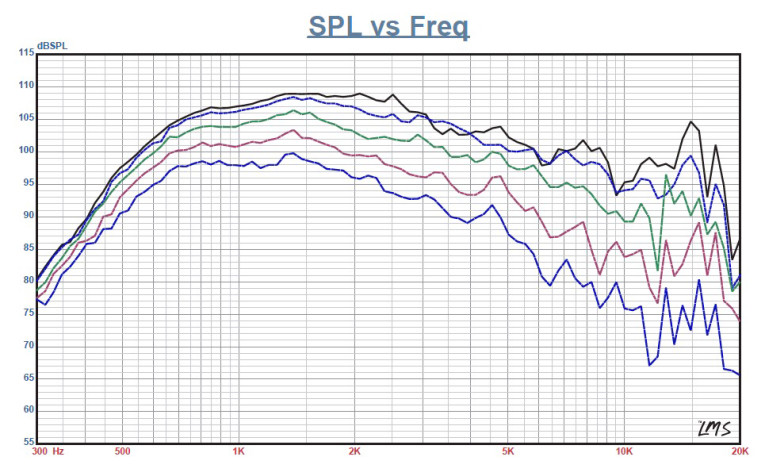
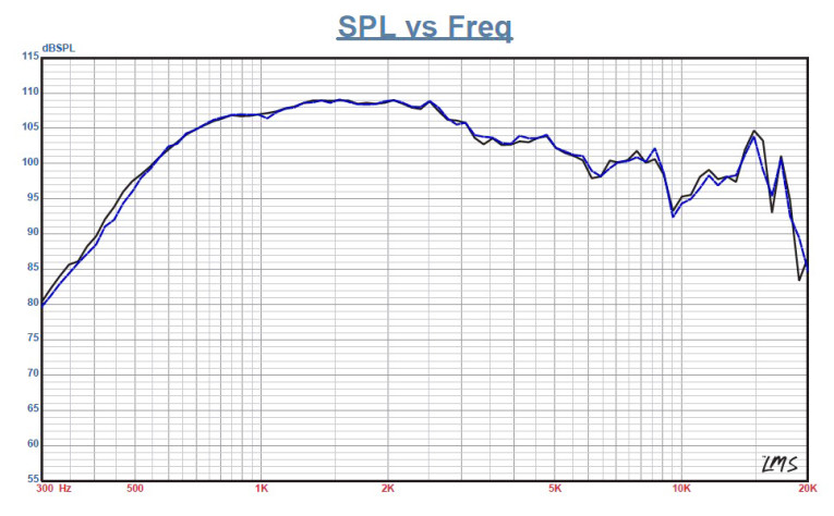
B&C Speakers recommends a 1.2-kHz crossover frequency for the 12FCX76 compression driver. Figure 13 shows the two-sample SPL comparisons for the 12FCX76 woofer samples, with both samples closely matched. For the 12FCX76 compression driver with the conical 80° horn, Figure 14 shows the on-and off-axis horizontal frequency response out to 60°. Figure 15 shows the two-sample SPL comparison for the 12FCX76 compression driver/horn, which is quite good throughout the entire frequency range.
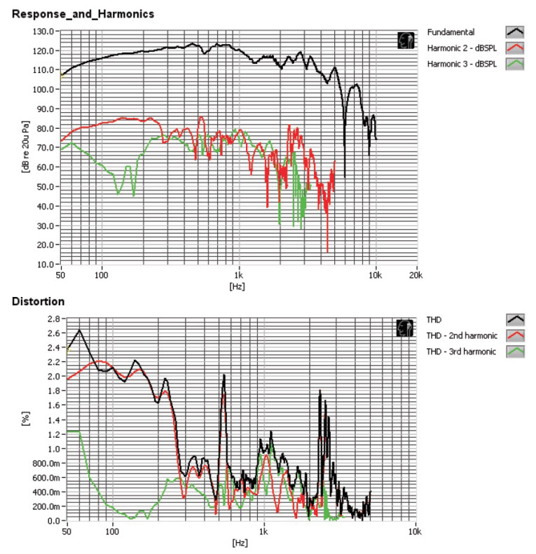
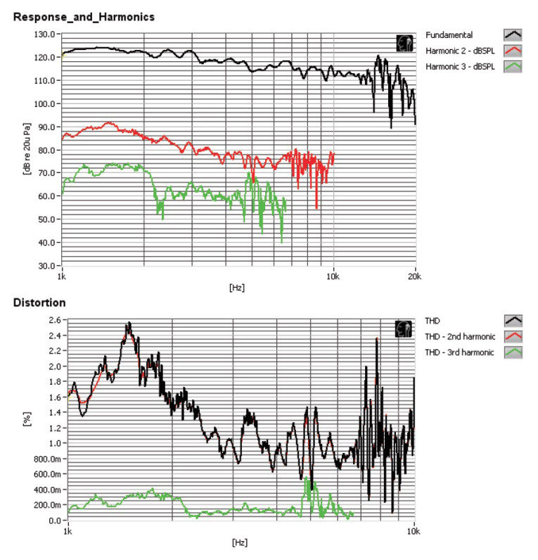
Last, I used the Listen SoundCheck analyzer and SC-1 microphone to measure distortion and generate time-frequency plots. I mounted the driver rigidly in free air and used the noise stimulus to set the SPL to 104 dB (SoundCheck’s utilities include a software generator and a SPL meter). I measured the distortion with the Listen microphone placed 10 cm from the dust cap/horn mouth. Figure 16 shows the 12FCX76 woofer’s distortion curves (7.9 V). Figure 17 shows the 12FCX76 compression driver’s distortion curves (2.82 V).
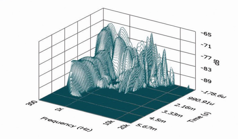
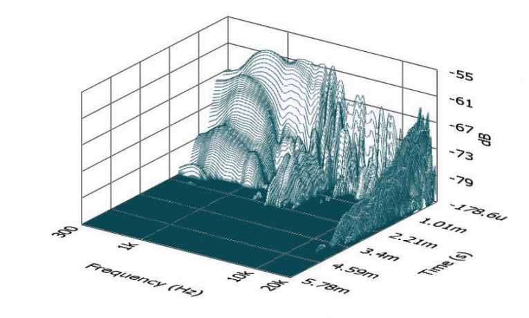
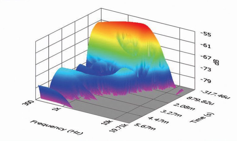
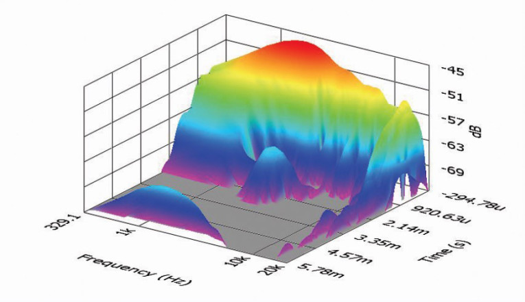
Following the distortion tests, I set up SoundCheck to produce a 2.83-V/1-m impulse response for 12FCX76 woofer and compression driver and imported the data into Listen’s SoundMap time-frequency software. Figure 18 shows the 12FCX76 woofer’s resulting CSD waterfall plot. Figure 19 shows the 12FCX76 compression driver’s resulting CSD waterfall plot. Figure 20 displays the 12FCX76 woofer’s Wigner-Ville logarithmic surface map (for its better low-frequency performance). Figure 21 shows the 12FCX76 compression driver’s short-time Fourier transform (STFT).
Overall, the 12FCX76 is a well-executed coaxial driver for pro sound applications (e.g., stage or studio monitors). For more information, contact B&C Speakers at www.bcspeakers.com. VC
This article was originally published in Voice Coil, July 2014.