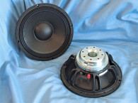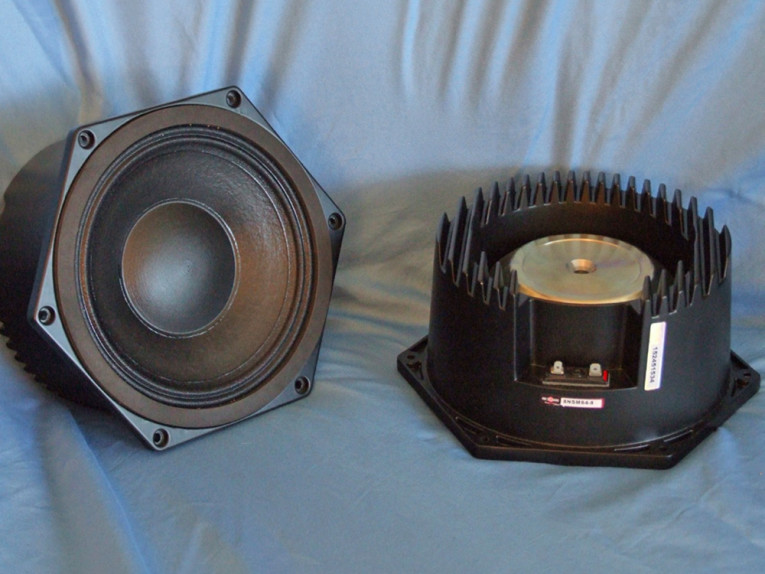
In this case, the 8NSM64 is a very high-power handling (500 W continuous) 8” midrange for professional PA applications. Photo 1 shows the interesting design concept that went into this product, producing a closed-back midrange with a reasonable volume that can be damped with absorption material. (I’m guessing foam or fiberglass.)
The 8NSM64’s feature set includes the proprietary cast-aluminum frame and the enclosure that incorporates a substantial heatsink, a curvilinear pulp formulated cone with a waterproof coating, a 3.5” diameter paper dust cap (also with a waterproof coating), a 65 mm diameter voice coil wound on a glass fiber former with aluminum wire, and a motor structure that incorporates a neodymium ring magnet with a T-shaped pole. Compliance is provided by a double roll M-shaped coated cloth surround and a single-cloth spider. Last, the voice coil is terminated to a pair of solderable terminals.
I began testing the 8NSM64 midrange using the LinearX LMS analyzer and VIBox to create both voltage and admittance (current) curves. I had the driver clamped to a rigid test fixture in free-air at 0.3, 1, 3, 6, 10, 15, 20, and 30 V.
Even though the 8NSM64 has only 1.5 mm XMAX (typical for a midrange), it stayed linear enough for LEAP 5 to get a curve on 30 V sweep, mostly due to the small closed-back enclosure. It should also be noted that this multi-voltage parameter test procedure includes heating the voice coil between sweeps for progressively longer periods to simulate operating temperatures at that voltage level (raising the temperature to the third time constant).
I post processed the 16 550-point stepped sine wave sweeps for each 8NSM64 sample and divided the voltage curves by the current curves (admittance) to create impedance curves, phase added using LMS calculation method. I uploaded the data, along with the accompanying voltage curves, to the LEAP 5 Enclosure Shop software. Besides the LEAP 5 LTD model results, I additionally created a LEAP 4 TSL model set of parameters using just the 1 V free-air curves.
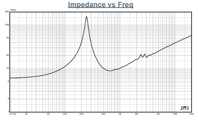
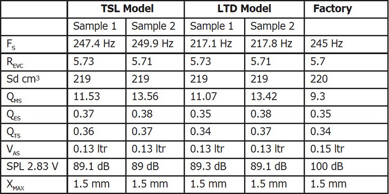
I selected the multiple voltage impedance curves for the LTD model and the 1 V impedance curve for the TSL model, and created the parameters to perform the computer box simulations. Figure 1 shows the 1 V free-air impedance curve. Table 1 compares the LEAP 5 LTD and TSL data and for both samples, as well as the factory parameters. The 8NSM64’s LEAP parameter calculation results were mostly in line with the B&C Speaker factory parameters, with the sensitivity number quite a bit different, notably because the SPL numbers from LEAP are a calculated mid-band sensitivity number, while B&C Speakers gets its number from an SPL measurement in the chamber. My SPL sensitivity at 2.83 V was identical to B&C Speakers’ number.
Now, it should be obvious that a midrange driver such as this will never get used in its piston range. Because of its small enclosure, it doesn’t really have a piston range and will probably be crossed over between 400 and 500 Hz. For this reason, there really isn’t any point in doing LEAP box simulations or Klippel analysis.
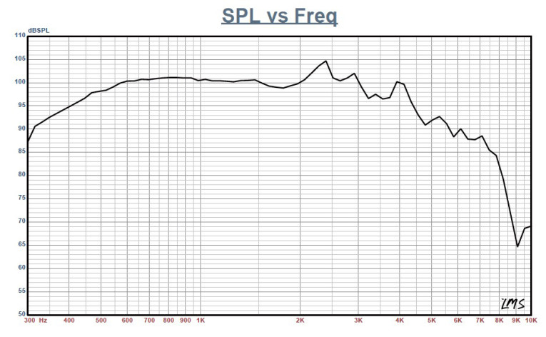
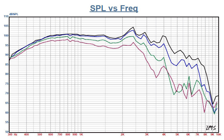
I moved on to the SPL and time domain measurements. Figure 2 shows the 8NSM64’s on-axis frequency response curve. The response is ±0.8 dB from 500 Hz to 2 kHz, with a 5 dB peak centered on 2.4 kHz, just as the driver low-pass roll-off begins.
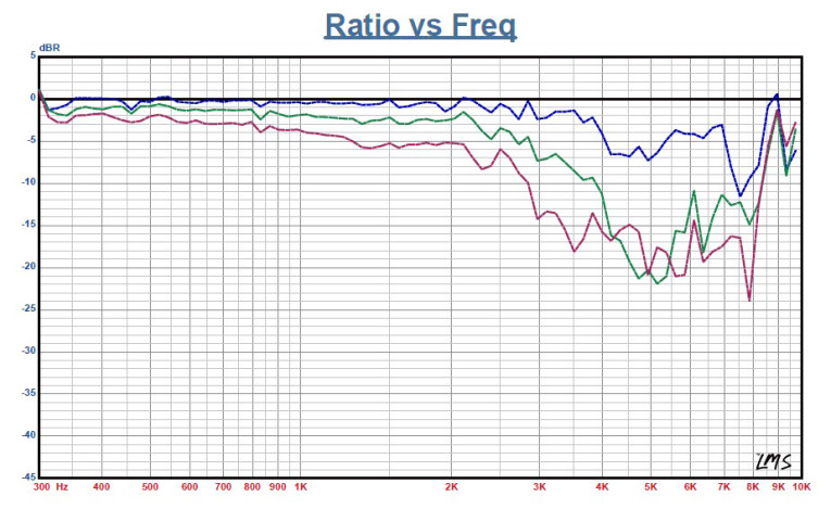
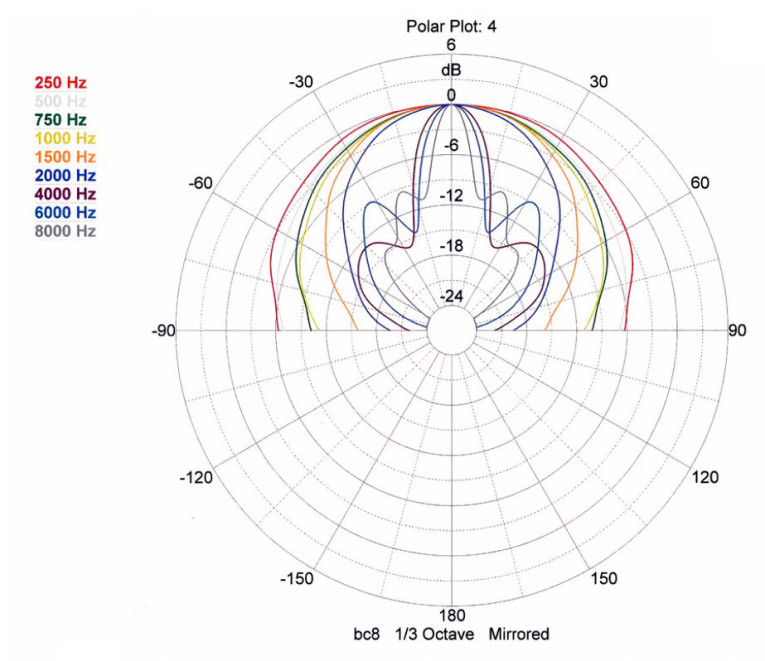
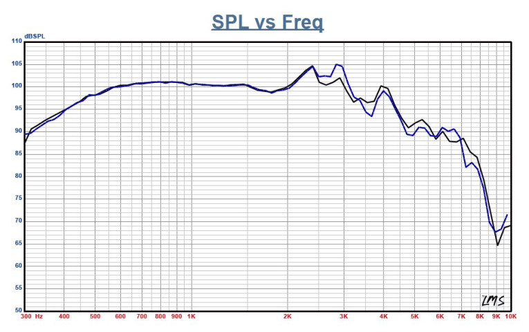
Figure 3 depicts the on- and off-axis frequency response at 0°, 15°, 30°, and 45° with the normalized view shown in Figure 4 and the associated CLIO polar plot shown in Figure 5 (with 1/3 octave smoothing). The –3 dB at 30°, with respect to the on-axis curve, occurs at 1.9 kHz, so a cross point in that vicinity should work well to achieve reasonable power response. Figure 6 shows the 8NSM64 two sample SPL comparisons, revealing a close match throughout its operating range up to about 3 kHz.
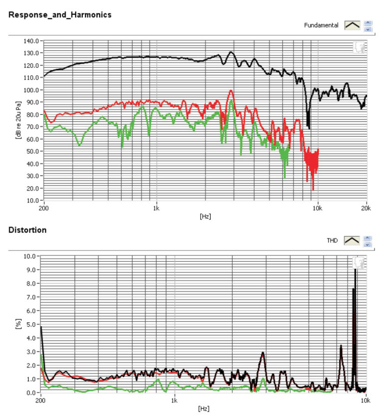
For the last group of tests, I employed the Listen SoundConnect analyzer and SCM-2 microphone to measure distortion and generate time-frequency plots. To set up the distortion measurement, I mounted the woofer rigidly in free air and used a noise stimulus to set the SPL to 94 dB at 1 m (7.184 V). Then, I measured the distortion with the Listen microphone placed 10 cm from the dust cap. This produced the distortion curves shown in Figure 7 (note this is now being displayed on a log scale).
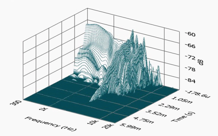
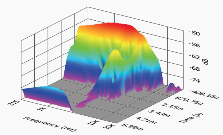
Last, I employed the SoundCheck analyzer to get a 2.83 V/1 m impulse response and imported the data into Listen’s SoundMap Time/Frequency software. Figure 8 shows the resulting CSD waterfall plot. Figure 9 shows the Wigner-Ville logarithmic surface map (for its better low-frequency performance) plot. After reviewing the data, I found this to be a well designed midrange for PA applications. For more information, visit www.bcspeakers.com
This article was originally published in Voice Coil, July 2016