In 2006, MAG began manufacturing speaker systems that range from small mobile sound systems and tiny public address speakers to large scale touring speakers and line arrays. MAG professional transducers include a range of cone loudspeakers with sizes from 6” to 21”, plus 1”, 1.4”, 1.5” and 2” high-frequency drivers and coaxial drivers. Besides manufacturing, MAG provides services in the development, installation, and maintenance of audio and lighting installations. MAG currently has 120 employees and a 30,000-ft2 production facility. About 60% of MAG production is exported. Production includes more than 500 tons a year of ferrite magnets, 20,000 units/year, spanning 50 models of transducers and 6,000 speaker systems a year with more than 60 models.
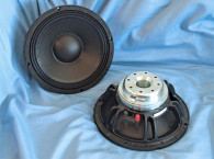
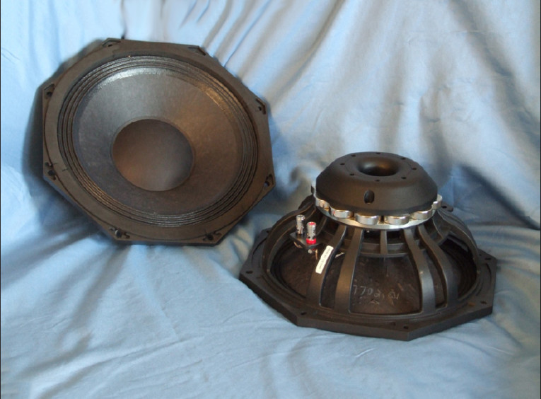
MAG’s 10N501 is a pro sound 10” woofer (see Photo 1). The 10N501’s intended application is for line arrays or compact two-way monitors. The 10N501’s features include a proprietary 12-spoke octagonal cast-aluminum frame that is open below the spider mounting shelf for cooling. The spokes form 12 11 mm × 8 mm vents for air flow on the forward end of the voice coil.
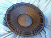
The cone assembly includes a lightweight curved profile uncoated paper/pulp cone, a 3.75” diameter uncoated paper dust cap, with a 3” (76 mm) diameter voice coil wound on a glass fiber former with an inside/outside winding (both sides of the voice coil former) that is wound with copper-clad aluminum wire. Compliance is provided by a three-roll pleated coated cloth surround and a 5.5” diameter cloth elevated spider (damper).
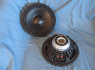
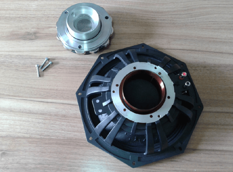
A removable self-centering motor system comprised of 12 28 mm × 8 mm polished neodymium slugs sandwiched between an 8 mm front plate and a two-part, cleverly designed T-yoke powers the motor (see Photo 2). The T-yoke assembly houses the dual shorting/demodulation rings as well as a 35 mm diameter pole vent accompanied by eight 5 mm diameter peripheral vents. Last, the voice coil tinsel lead wires terminate to pair of color-coded chrome push terminals.
I began testing with the 10N501 clamped to a rigid test fixture in free air. I used a LinearX LMS analyzer and VIBox to produce both voltage and admittance (current) curves at 0.3, 1, 3, 6, 10, 15, 20, and 30 V. I post-processed all 16 of the 10 Hz to 20 kHz 550-point stepped sine wave curve pairs for each sample and divided the voltage curves by the current curves, creating the eight impedance curves. I applied the LMS phase calculation procedure to each of the impedance curves and imported the data, along with the voltage curve for each sweep, to the LEAP 5 Enclosure Shop CAD program.
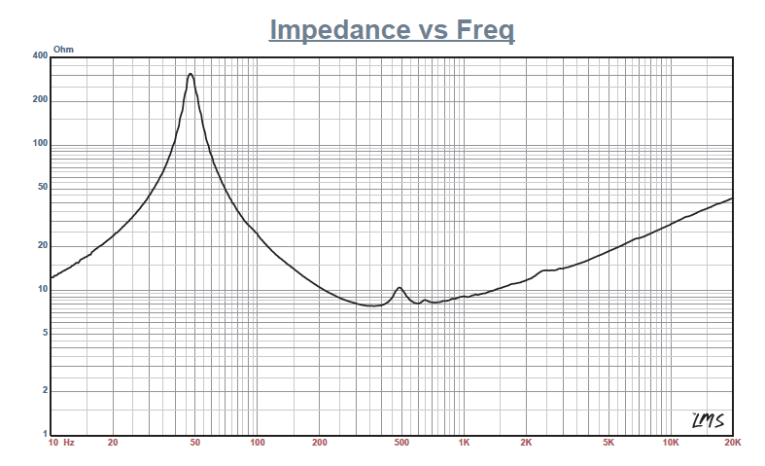
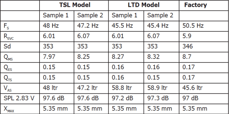
Since most T-S data provided by OEM manufacturers is produced employing either a standard T-S model or the LinearX LEAP 4 TSL model, I additionally created a LEAP 4 TSL model using the 1 V free-air curves. I selected the complete curve set, the multiple voltage impedance curves for the LTD model, and the 1 V impedance curves for the TSL model in LEAP 5’s transducer derivation menu and created the parameters for the computer box simulations. Figure 1 shows the 1 V free-air impedance curve. Table 1 compares the LEAP 5 LTD and TSL data and factory parameters for both 10N501 samples.
The 10N501’s T-S parameter results correlated with the factory published data. That said, I programmed computer enclosure simulations using the LEAP LTD parameters for Sample 1 to create a 250-in3 closed box with 50% fiberglass fill material and a larger 0.58-ft3 vented box alignment tuned to 48 Hz with 15% fiberglass fill material.
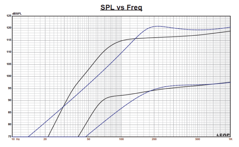
Figure 2 depicts the 10N501’s results in the sealed and vented boxes at 2.83 V and at a voltage level sufficiently high enough to increase cone excursion to 6.15 mm (XMAX + 15%). This calculation resulted in a F3 frequency of 168.5 Hz (F6 = 129.5 Hz) with a QTC = 0.6 for the 250-in3 sealed enclosure and with –3 dB = 64 Hz (–6 dB = 57 Hz) in the 0.58-ft3 ported box simulation.
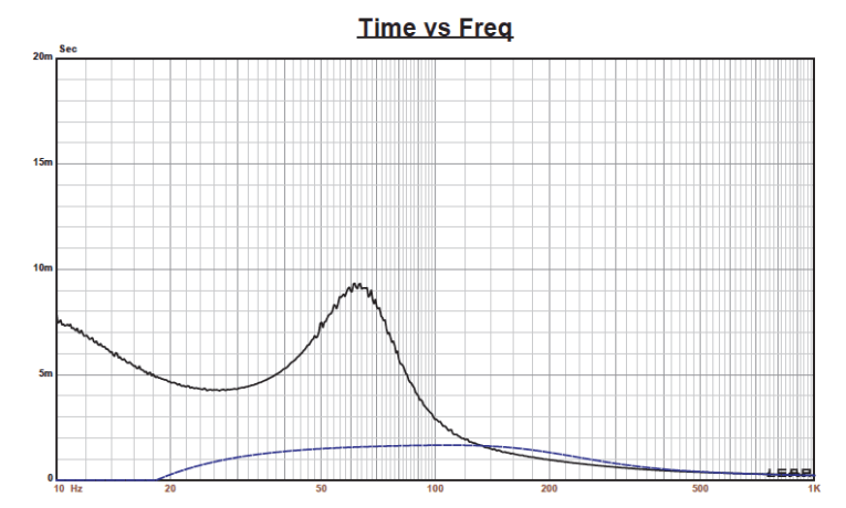
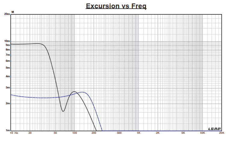
While the QTC is low and the closed box is rather small for this driver, it would be appropriate in a line array with a 200 to 250 Hz high-pass filter. Increasing the voltage input to both simulations until the maximum linear cone excursion was reached resulted in 121 dB at 60 V for the smaller sealed enclosure and 116 dB with a 40 V input level for the larger vented box. Figure 3 shows the 2.83 group delay curves. Figure 4 shows the 60V/40V excursion curves. It should be obvious from the excursion curves that the sealed box incarnation would be thermally limited, not excursion limited.
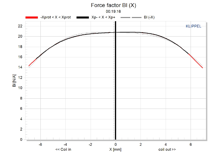
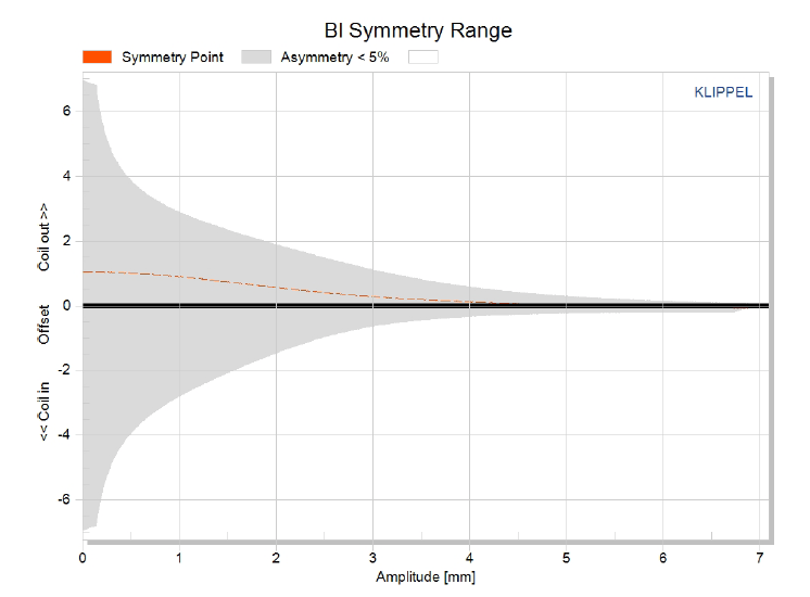
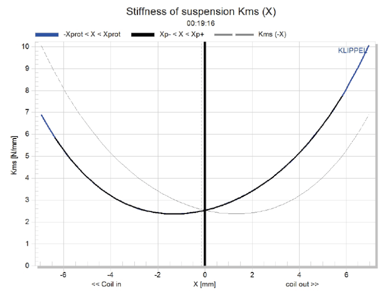
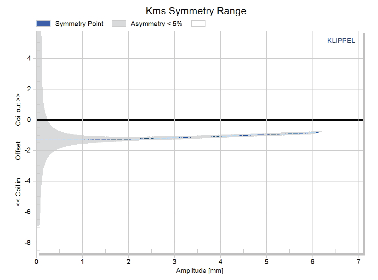
The 10N501’s Klippel analysis produced the Bl(X), KMS(X), and Bl and KMS symmetry range plots shown in Figures 5-8. The 10N501’s Bl(X) curve is nicely broad and symmetrical (see Figure 5). Looking at the Bl symmetry plot shows no offset from 3.5 mm (where the area of certainty is resolving) out to the 10N501’s physical XMAX (see Figure 6). Figure 7 shows the KMS(X) curve, which is rather asymmetrical but with some obvious offset. Figure 8 shows the KMS symmetry range curve. There is 1.28 mm of forward coil-in offset at the 1 mm position, which stays fairly constant out to the10N501’s physical XMAX, suggesting the driver voice coil is not physically aligned with the magnetic center in the gap. This is not extreme and you would have to take a reasonable sample of a production run to determine is this was a consistent issue or not. Either way, this type of minor magnetic gap displacement is not subjectively a problem.
The 10N501’s displacement limiting numbers, which were calculated by the Klippel analyzer, were XBl at 70% Bl = greater than 5.8 mm and for XC at 50%, the CMS minimum was 3.9 mm, which means the compliance is the most limiting factor at the prescribed distortion level of 20%.
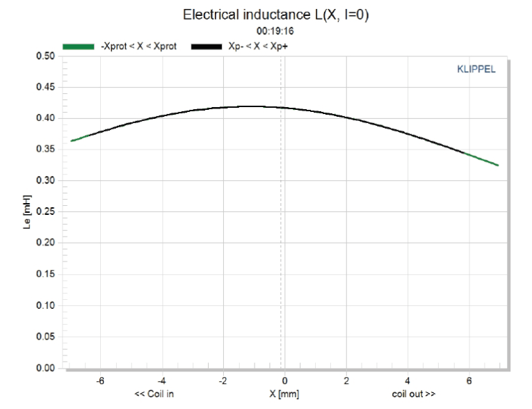
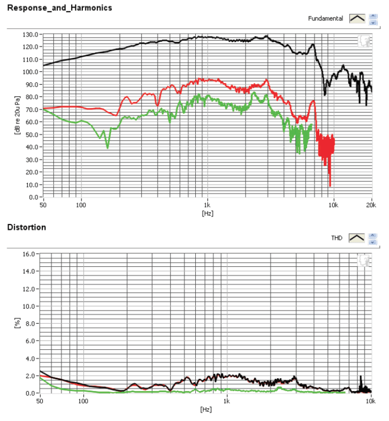
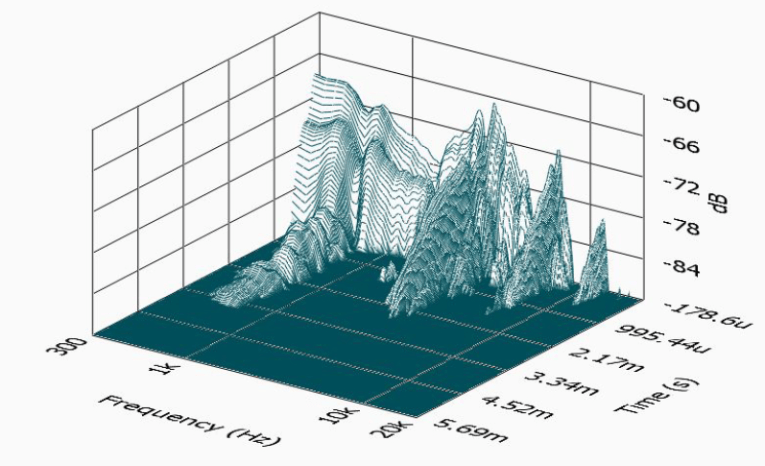
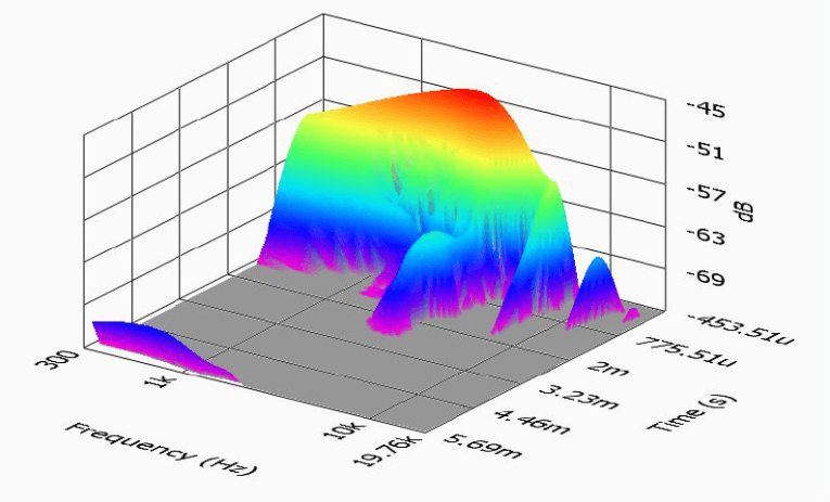
Figure 9 gives the 10N501’s inductance curves L(X). Inductance will typically increase in the rear direction from the zero rest position as the voice coil covers more pole area, which not what you see with this style of motor. From XMAXOUT to XMAXIN, the inductance range is only 0.029 mH to 0.065 mH, which is obviously a small inductive shift. This is very good performance and is the result of the 10N501’s dual shorting ring configuration.
Next I set up the Listen SoundCheck AmpConnect analyzer for distortion measurements. Using a noise stimulus, I set the SPL 104 dB (7.29 V) at 1 m with the 10N501 mounted in an enclosure in free air and placed the microphone at 10 cm. Figure 10 shows the 10N501’s distortion curves. Then, I mounted the 10N501 in an enclosure with a 17” × 11” baffle and took the impulse measurement. I imported the data into Listen’s SoundMap software, windowed to remove the room reflections, and produced the CSD waterfall plot shown in Figure 11 and the Wigner-Ville plot shown in Figure 12.
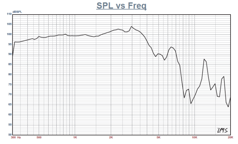
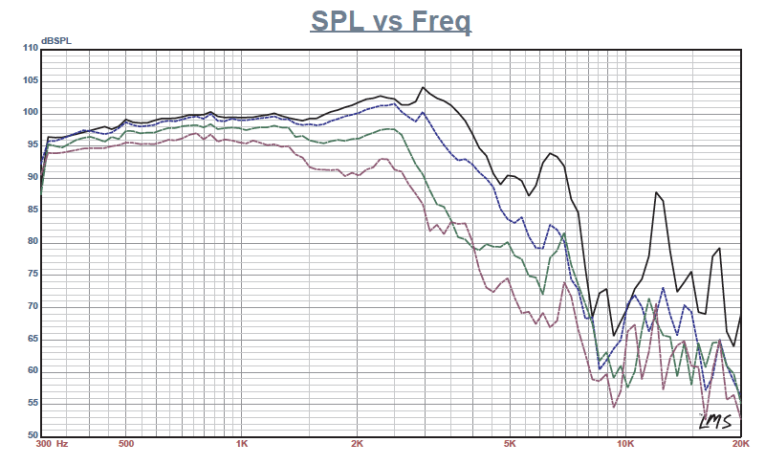
For the remaining SPL measurements, I used the same enclosure and measured the driver frequency response both on and off axis from 300 Hz to 20 kHz with a 100-point resolution at 2.83 V/1 m, using a gated sine wave method with the LinearX LMS analyzer. Figure 13 depicts the 10N501’s on-axis response, yielding a smooth rising response out to 2.5 kHz followed by a small 2 dB peak at 3 kHz just prior to the low-pass roll-off. Figure 14 shows the on- and off-axis frequency response at 0°, 15°, 30°, and 45°. The –3 dB at 30° with respect to the on-axis curve occurs at about 1.5 kHz, which is in the vicinity of the typical 1 to 1.5 kHz crossover for 10” drivers.
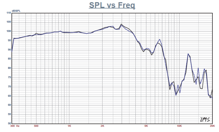
Figure 15 gives the 10N501’s two-sample SPL comparisons, showing both samples closely matched. The 10N501’s overall fit and finish and build quality is really excellent, suggesting MAG should be a good contender in the pro sound driver arena. For more information, visit mag-audio.com/transducers/.
This article was originally published in Voice Coil, January 2016.