Disappointing Subwoofer
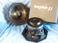
Some years ago, I made two subwoofers designed by my local speaker shop. The enclosure was a bass reflex with 81 ltr internal volume. The driver was a 10” Beyma 10B60 (Fs 31Hz, Qts 0.36, Vas 115 ltr, and Sd 380cm2).
I was not happy with the result: nothing below 30Hz, port noise, and problems with uneven frequency response due to room resonances. Furthermore, these cabinets are not easy to hide away. Actually, they were hidden away. Far away.

Transmission Line Sub
Twenty years ago, I built horns like everybody else at that time. The horns were quarterwave designs with expand one third of the line. Quarterwave designs are not outdated at all, as I found out by reading articles by Rick Schultz. I wanted to design and build a transmission line (TL), which is the term I use for all types of quarterwave design. Because I had two bass reflex speakers, I would be able to compare the TL sub against the vented enclosure.
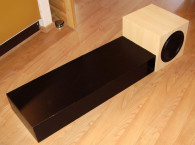
My idea was to mount the driver in a small box and let the pipe itself be smaller, so I could hide it under the couch. Of course, this would reduce the volume of the cabinet, and you could expect a weak bass. But because both the opening and the driver are close to the floor, I hoped to get a lift in the deep bass. With the opening at the front, you could even place the sub in a corner to get maximum room gain. I ended up with this design, using a small opening, to be able to place the cabinet just about anywhere (Fig. 1).
The box itself should not be very visible. The size of the rest of the cabinet was dictated by the space under my couch. I made the opening small, set to about 20% of the cross section (and thereby 10% of the derived Sd). The total length of the pipe is 230cm, and I assumed, the pipe was tuned to about 37Hz. But I soon found out this was not the case.
I used relatively thin material and included a cross bracket in the box. The front baffle is 22mm MDF. The stuffing is relatively light in the box and for the first line of the pipe only.
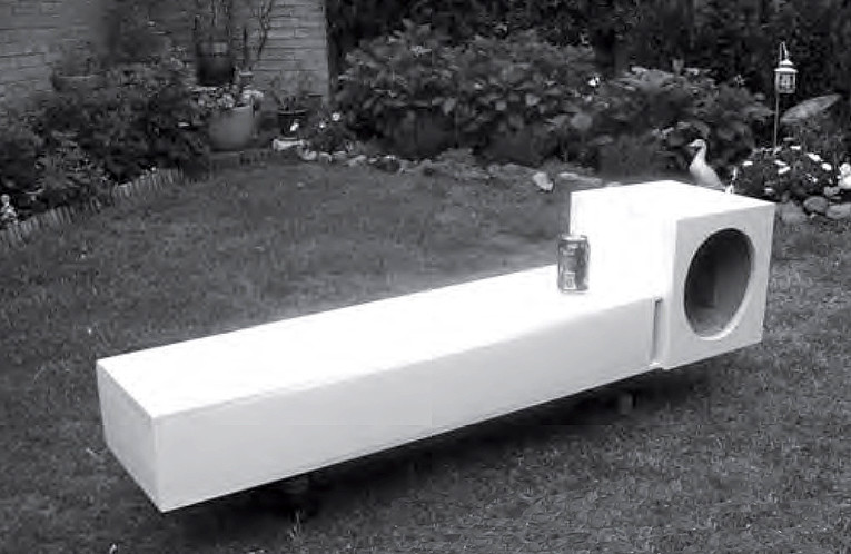
The Result
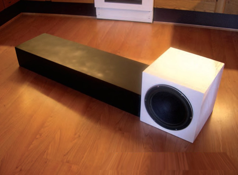
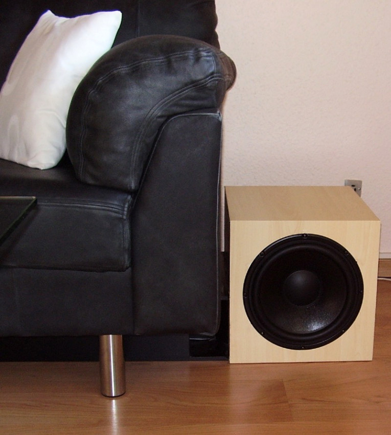
Photos 1 and 2 show the working unit. In comparison with the vented box, the Hideaway bass is lower, clearer, and tighter. There is no noise caused by turbulent air in the opening. The cone motion is reasonable down to 20Hz, but at 16Hz the movement increases. There is still output at 16Hz, even though the output drops from 20 to 16Hz. This surprised me. It was clear that the tuning frequency of the pipe was lower than I had expected and lower than the driver Fs. I wanted to find out what was happening.
Tuning Frequency
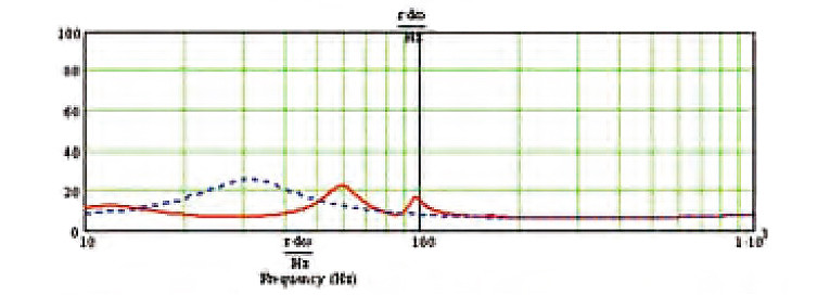
I started to study the work of Martin J. King, who has been very helpful and patient with my questions (see sidebar). I could see that the tuning frequency was about 25Hz, and by the use of Martin’s worksheets, which can be used for private and non-commercial purposes, I learned what was going on.
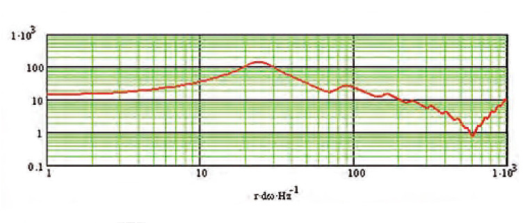
If the line had been a straight line, the tuning would be around 37Hz. Actually, the Hideaway enclosure behaves like a mass-loaded TL with a port, which lowers the tuning frequency of the cabinet. The plot from Martin’s worksheets, acoustic impedance of the cabinet, showed the tuning frequency was about 25Hz (Fig. 2). The first peak is at 25Hz, which is the tuning frequency of the cabinet alone.
Sound Pressure Level (SPL)
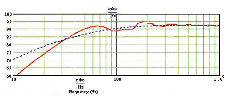
The dotted line in Fig. 3 is the driver in an infinite baffle (IB). The SPL might look poor, but because the driver and the opening are at the floor, there is a good deep bass performance in the listening room. Because this is a sub, I do not worry about the uneven frequency response above 100Hz, which will be eliminated by the crossover filter.
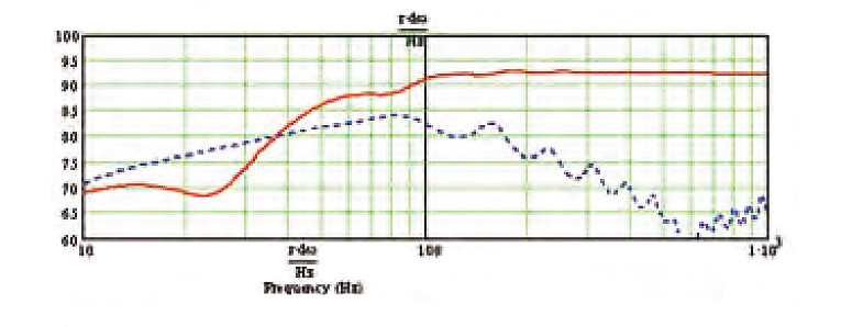
In Fig. 4, the solid line is the driver, and the dotted line the opening. As you can see, the opening is adding at lift to the bass where the driver is rolling off. The output from the aperture is broad and flat. Also notice the fall output from the opening, with a rolloff starting at about 85Hz. The relatively small volume and the mass loading by the small opening opening causes this unique behavior of the output from the opening.
Impedance
In the Fig. 5 plot, the enclosure is not stuffed, to make the impedance peaks more visible. With stuffing the impedance curve becomes very flat, and some of the peaks hard to see. The dotted line is the driver in an IB. The solid line is the combined enclosure and driver, forming the new resonance system. The first resonance (impedance peak) just below 15Hz is a combination of the air mass in the pipe combining with the moving mass of the driver cone and voice coil oscillating on the driver’s suspension. Very much the same as the old trick of lowering the driver Fs by adding some physical mass to the cone.
The second resonance peak about 60Hz is the original cabinet resonance, but with the influence of the driver. The rolloff from the opening is about 85Hz, which corresponds to the dip in the impedance curve between the second peak at about 60Hz and the third peak at about 98Hz.
A Generic Design
I have modeled several other drivers in the Hideaway enclosure, and while this versatile design does not necessarily get the very best of each individual driver, the drivers I have simulated are all doing fine. The tuning frequency of 25Hz is a reasonable value for drivers with a Fs of 35Hz and below. A driver with the same Fs, but higher Qts and lower Vas has a little improvement in the deep bass, due to the later rolloff.
The Peerless 830452, with the very low Qts of 0.17, is also doing well. In this case the cabinet tuning is higher than the driver Fs of 18.9Hz, which is a good combination for a low Qts driver, which has an early rolloff.
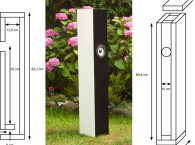
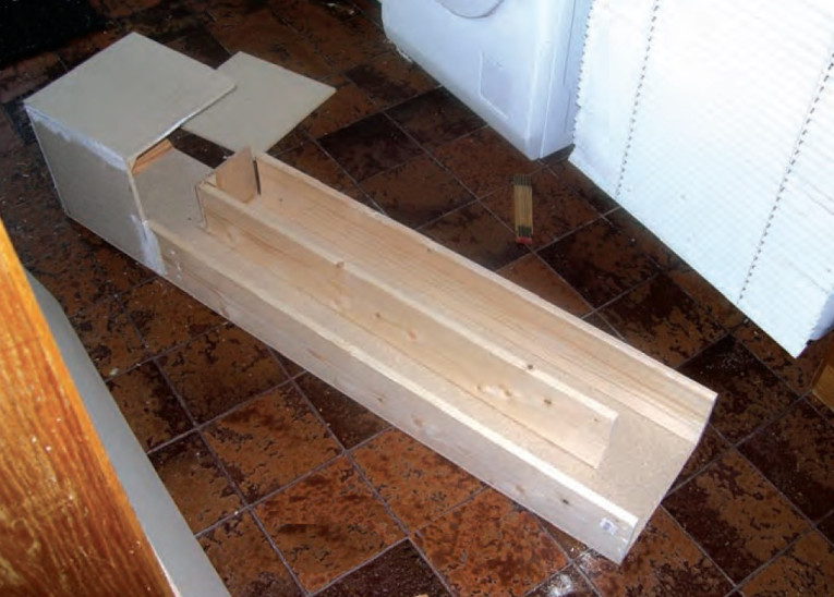
Construction
Figure 6 gives the unit’s external dimensions. In addition, the line length is 230cm, internal dimensions of the box are 29 × 29 × 29cm, and cross section in the pipe is 12.8 cm (width) × 15 (height). The footprint is 30 × 140cm using 10mm particleboard.
Front baffle is 22mm MDF, which then extends the footprint in this end. The box uses 10mm particleboard, with 10mm MDF added inside to reduce vibration. The box also has a cross bracket inside. The “labyrinth” walls measure 150 × 14mm. I added triangular pieces of wood in all corners. The labyrinth is closed on the top with 10mm particleboard (Photo 3).
The box measures 32 × 32 × 32cm externally, and by placing a piece of glass on the top, the box becomes a nice little table. Photo 4 gives you an idea of the cabinet size. Stuffing in the box and the first half of the labyrinth is 200g of polyester wool.
Design Considerations
Designing a TL is a challenge, because you have many parameters to work with. But this is also the reason TL design is great fun. I use a design idea as a starting point; I do not choose a driver, and try to find the best design possible. Trying to achieve maximum performance of a driver most likely would result in a cabinet size and shape you probably would not like to place in your listening room. Designing a TL is a recursive process, with the goal of finding the best compromise.
Tuning Frequency
The most important design parameter is defining the tuning frequency of the cabinet. If you increase the tuning frequency, the output level from the opening will increase. And when you lower the tuning frequency, the output level will, not surprisingly, decrease.
The output from the opening is a desired property of the TL, adding a lift to bass. If your driver has a high Qts, you below driver Fs. Low Qts drivers have an earlier rolloff; therefore, you could set the tuning frequency higher than driver Fs.
I use a Qts of 0.35 to distinguish between high and low Qts. This is not the “only truth,” and your definition might be different. Therefore, the tuning frequency is below the Fs of my Beyma driver.

with 2cm added by the front baffle.
Once you have a tuning frequency in mind, you must decide which geometry to use. Length and geometry sets the tuning frequency of the cabinet. Increasing the volume will increase the bass. Increasing volume also influences the tuning frequency a little. The Hideaway would have had a tuning frequency of 37Hz if it were a straight pipe. But the reduced volume in the pipe and the reduced opening result in a lower frequency. You could call it a ported, mass loaded, tapered quarterwave. But the label on the design is not important to me.
Tuning frequency is set by the length of the line and the geometry. For a straight line, it is simply a quarterwave of the frequency. A tapered line (opening has a smaller area than the closed end of the pipe) is the smallest possible enclosure for the same frequency.
A tapered line is used to tame unwanted upper harmonics. The output from the opening is broader and with slightly less output, compared to the straight line. An expanding line is the longest line for the same tuning frequency. It has a high output level; unfortunately, the frequency curve is very uneven. If you mass-load the straight line — by making the area of the opening smaller than the cross section — the line will be shorter than the straight line for the same tuning frequency. Volume will, in general, increase the bass and also lower the tuning frequency a bit.
Problems with TL
The resonance of the pipe is what you want. The other, higher resonances cause dips and peaks in the SPL and are definitely unwanted. A common way to tame the upper harmonics is to use a driver offset down one-third of the pipe. This was not an option in the Hideaway design.
Stuffing is also used to damp the uneven SPL and to smooth the impedance curve. On the other hand, I do not want to attenuate the opening. Therefore, I use light damping in the box and only half of the line. In a sub the crossover will get rid of the ripples, anyway. Please note that damping has very little to do with the acoustic impedance (tuning frequency) of the cabinet. In fact, your local altitude above sea level and the temperature of the air has more impact on the speed of sound, and thereby the resulting tuning frequency, than stuffing.
Conclusion
The Hideaway TL has some very useful properties:
• It is very practical, and does not take up much space.
• The location of the opening allows for the pipe to be hidden.
• Allows for placement against the wall or in a corner.
• With the opening and the driver close to the floor, the deep bass SPL is very good for an enclosure of this size.
• Can be used with a variety of drivers with Fs at 35Hz and below.
• Very good damping of the cone excursion.
Acknowledgment
I would like to thank Martin J. King for the help in understanding his quarterwave design (see sidebar).
This article was originally published in audioXpress, July 2006
Bjorn Johannesen is an avid DIY hobbyist from Denmark, involved in building amplifiers and loudspeakers. His speaker designs have included horns, full-range, and transmission lines. The interest in quarterwave designs has accelerated in the last few years, thanks to audioXpress, www.t-linespeakers.org, and www.quarter-wave.com. See more from this author here.
And his successful venture: www.kvart-bolge.com
Martin J. King’s Mathcad Worksheets
From Martin J. King’s website (www.quarter-wave.com), you can download Martin’s worksheets, available for your private, non-commercial use on MathCad. I always use the “Sections” worksheet, and you can model the Hideaway with your favorite driver. The geometry definition I use is somewhat simplified. I have not defined the corner in the pipe as a separate section, but this is not important at low frequencies.
The plots in this article use the following input, and it is very useful to benchmark different drivers. Type in the Thiele/Small parameters (TSP) for your driver, including BL. You can use one of the worksheets to convert from Vas to BL, if you do not know the BL value.
I recommend you measure your driver’s Thiele/Small parameters. You should not expect that your driver’s parameters will necessarily match the ones documented by the manufacturer.
Note: Martin uses “d” (driver) instead of “s” (speaker), so Vad = Vas, and so on. I find Martin’s terminology more logical than the original TSP abbreviations. Set n_closed := 0 and n_open:= 3 in the worksheet. Then define the geometry.
Driver to closed end:
| LENGTH | CROSS SECTION START | CROSS SECTION END | STUFFING |
| 5.5” | 2.21 Sd | 2.21 Sd | Y |
Driver to open end:
| LENGTH | CROSS SECTION START | CROSS SECTION END | STUFFING |
| 5.5” | 2.21 Sd | 2.21 Sd | Y |
| 39.5” | 0.51 Sd | 0.51 Sd | Y |
| 39.5” | 0.51 Sd | 0.51 Sd | N |
| 0.6” | 0.11 Sd | 0.11 Sd | N |
The last section is the opening, with the length = dimension of the wood used. Total line length is 90.6”. Stuffing is 0.3 lb per ft3. The pipe is divided into two sections to distribute the stuffing. I used 200g of polyester wool in the box and the first half of the line.
Cross section is defined by Sd because it is easier to type in and also gives me a good feeling of the size of the cabinet. In my example, Sd = 380cm2. You can adjust the input to your drivers. The pipe tuning is 25Hz. You can check your input in the first plot in MathCad: In the acoustic impedance the first, and highest, peak is at 25Hz.
Internal geometry of the cross section is:
| 2.21 Sd | 29cm × 29cm | 11.417” × 11.417” |
| 0.51 Sd | 12.8cm × 15cm | 5.039” × 5.906” |
| 0.11 Sd | 2.8cm × 15cm | 1.102” × 5.906” |
Beyma in Bass Reflex
I had the opportunity to compare the Hideaway with a vented design with the same driver. The bass reflex has a higher SPL, but output dropped from 35Hz to 30Hz, and below 30Hz there was no sound. The cone excursion increased under 35Hz, and this construction should have had a high-pass filter. Compared to this bass reflex, the cone motion of the Hideaway TL is very well damped. This sound pressure level might look impressive (Fig. 7), but the frequency is very elevated due to room gain, and this “boomy” sound is not nice at all. There is no deep bass, and the rolloff is like falling off a cliff.
Furthermore, this construction suffered from port noise.