Twenty years ago, the Klippel R&D measurement system started with identifying the nonlinearities that occur when the final mounted speaker is driven to high levels. Going backward from the large signal behavior, the small signal parameters can be determined by most of the loudspeaker measurement systems. In addition to a wide repertoire of measurements for complete speakers, Klippel developed measurement solutions dedicated to analyzing loudspeaker parts before they are glued to search for physical characteristics related to the construction. In this case, the important information is at the bottom of the magnetic gap. With a thin Hall Effect sensor, which is available as an accessory for the Klippel R&D system associated with the Distortion Analyzer 2, it is possible to measure physical basics for the movement of the loudspeaker cone. The magnetic flux density can be directly measured at various positions inside or outside the gap.
as hand-held gaussmeter.
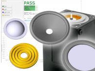
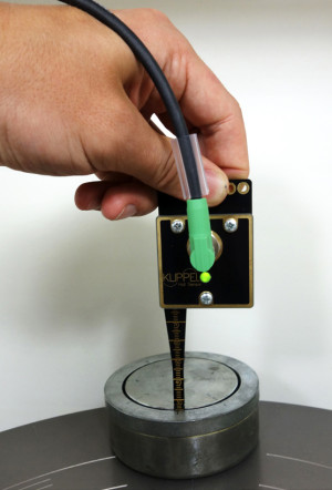
For testing the polarity of a magnet or its maximum magnetic flux density, a simple and robust hand-held probe is a convenient tool (see Photo 1). Assumptions of symmetry and homogeneity are often incorrect. Not only does this raise questions, it also creates the need for measurement solutions more powerful than a hand-held B-field probe.
It can be assumed that the electrical field around the voice coil is axial-symmetrical. But is the B-field in which the voice coil interacts also symmetrical? Are placement tolerances of the pole piece a factor? How does inhomogeneous material influence this?
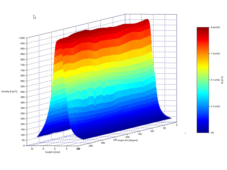
The goal of the magnet construction is to concentrate the magnetic flux into a constant field in the area of the pole plate. But this depends on more than just the dimensions of the pole plate and pole piece. How symmetrical is it in reality? Has the magnet simulation considered all construction aspects? A measurement of the B-field over the height of the voice coil gap and above can properly diagnose this issue. Finally, this can be combined into one automatic 3D B-field measurement that analyzes and visualizes the magnet flux density distribution over height and angle (see Figure 1).
Fo3D B-Field Analysis
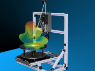
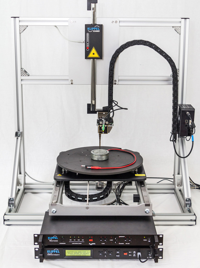
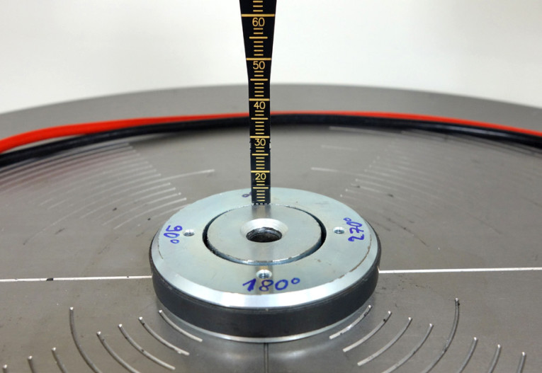
For an automatic measurement, the B-field sensor gets moved through the magnet gap. The height and the angle is controlled by the system. The Klippel Scanning Vibrometer moves a laser displacement sensor over the cone profile to measure the cone vibration over the complete loudspeaker. It is intuitive to use the same three-axis hardware to move a B-Field sensor through the gap (see Photo 2).
Similar to the cone scanning process, the turntable moves the magnet to control the angle of the measurement. The height is controlled by the Z-axis of the Klippel Scanning Vibrometer. The radius can be manually adjusted by using the R-axis, while the Cone Scanning automatically controls it.
To measure a magnet, the user can manually adjust the sensor to the radius of the gap or use setup parameters to bring the sensor to the desired measurement start coordinates. The user only has to define a few setup parameters to control the automatic scanning process. Step sizes in angle and height have to be selected and the height of the measured B-field range has to be defined. With a tick-mark, the resolution can be doubled in the center region, which is typically the region of highest interest regarding the loudspeaker’s performance.
Post-Processing Dedicated to Loudspeakers
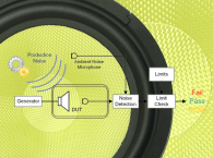
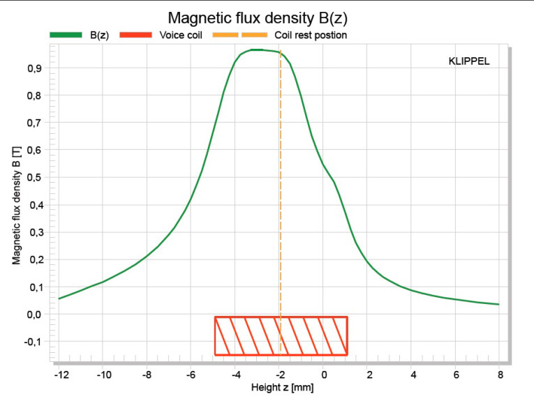
Different gaussmeters are available on the market. A 2D solution for measuring the B-field over height Z is to automatically pull the sensor out of the voice coil gap (see Figure 2). The device can be easily built with available hardware. However, the big advantage of the B-Field Scanner (BFS) is an automatic 3-D measurement process combined with visualization of the results and a post-processing dedicated to loudspeakers, putting this system in line with other Klippel measurement techniques on complete loudspeakers.
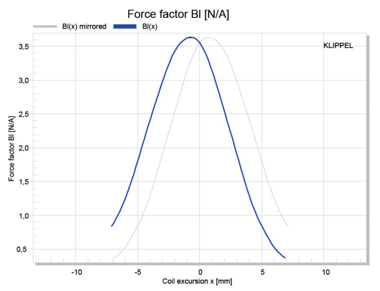
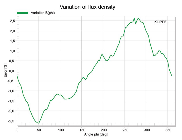
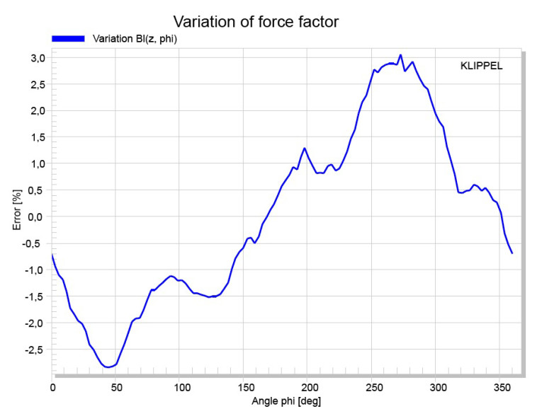
To calculate the force factor Bl(x) over voice coil position x (see Figure 3), the user can define the properties of the voice coil such as physical dimensions (radius, height), and number of windings and winding layers. The software also calculates the Bl variation over angle φ, similar to the variation of the measured B-field (see Figure 4). The nonlinear curve Bl(x), determined with the dynamically large signal measurements (LSI), can easily be compared to the simulated Bl(x) curves from the static B-field measurement. Additionally, the post-processing enables the user to analyze the influence of the coil rest position on the resulting Bl(x) and variation Bl (φ) and visualizes the effects.
The variation over the angle φ may be the root cause of an unexpected speaker behavior (e.g., a rocking mode) as shown in Figure 5. An asymmetrical B-field produces an asymmetrical force. Whether this asymmetry will cause an undesired behavior depends on other aspects (e.g., the suspension of the driver, its dimensions, and displacement in usage). In addition to this new physical analysis method, a cone scanning post-processing is under development that can analyze rocking modes with the laser scanning technique. This will indicate if the rocking is caused by a Bl asymmetry, a stiffness asymmetry, or mass imbalance, as well as the angle at which the problem is located.
The Sensor is the Key
The magnetic gap needs to be as narrow as possible to provide a maximal B-field for an effective loudspeaker. Thus, the sensor also needs to be narrow (see Photo 3). A sensor thickness of 0.65 mm combined with the semi-flexible, robust construction of the sensor strip makes it suitable for a wide range of magnets. Actually, it is difficult to find a thinner sensor on the market.
To answer the initial question, in one sense it is just a magnet, but it is as important as every other part of the loudspeaker. Therefore, it should get its own measurement technique. With a clever combination of measurements at the final speaker assembly and as pre-assembled parts, acoustical behavior can be traced back to physical characteristics and properties. VC
This article was originally published in Voice Coil, May 2017.