This “little” amp is easy to construct and has only about 25 parts in each channel. The system transformers are very inexpensive, and the total cost involved for a complete stereo version should be very minimal! Most of the parts used in this project are available from Antique Electronic Supply. The tubes involved are the least costly of most name brands that I could find and yet they will still deliver the sound that vacuum tubes are noted for.
The voltage amplifier and phase inverter tube is a 12SL7, and the outputs are 12V6s. These tubes have the same electrical characteristics as their counterparts — the 6SL7 and the 6V6. The only difference, of course, is the heater voltage. With the type of transformer used for the power supply, and with the help of one small 12.6V transformer, the tubes will be supplied with all of the necessary voltages to operate the amplifier.
Again, as in my 6550 single-ended amp project (Sept. ’01 audioXpress), this article does not contain any complex math. It gives you only the information you need to complete the amplifier. No special or “high end” components are used because I don’t believe that a beginner in this hobby should suffer “sticker shock” when starting his/her first project.
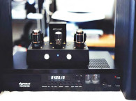
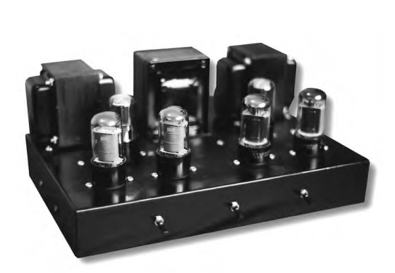
If you wish to experiment and try different capacitors, resistors, or other components, in order to obtain a better sound, please feel free. After all, this hobby is all about having it your way. The amplifier (Photo 1), when constructed with the parts listed, gives a warm and full range of sound and will be pleasing to most new hobbyists—especially those of you used to listening to small solid-state equipment.
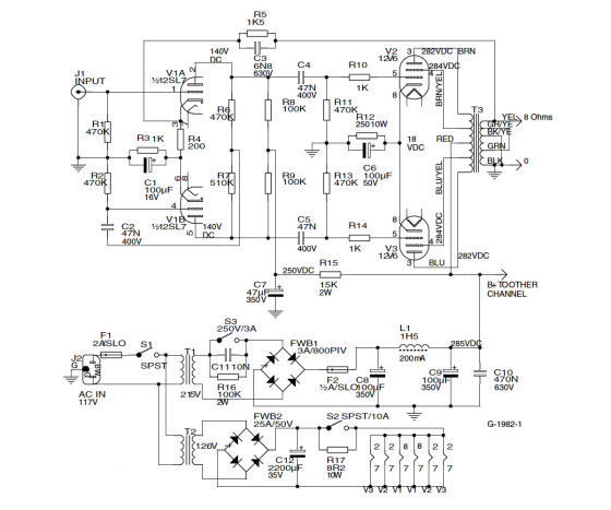
It has the kind of sound that tubes are famous for and gives an output of just around 12W of power per channel. This is actually more than the famous single-ended 300B will deliver, even though the 300B is in a class all its own. The amp will drive most speakers with an efficiency of 90dB or more to a room-filling volume. For a first-time project and introduction to the types of circuits involved with tube audio, the results should be very rewarding indeed. If you follow the schematic diagram (Fig. 1) and use careful construction techniques, the amp will work when you first power it up and should give you years of listening enjoyment. It will also be very easy to service and repair in the future because you built it yourself!
Circuit Description
The circuit here is very simple and yet is effective for the types of tubes used. These 12V6s operate in push-pull class AB1 with around 285V on the plates and will give you the warm, rich, and classic sound of the amplifiers from many years ago. It was used, in the 6V6 version, in the same types of circuits as the 6Y6 and the EL84.
All of these tubes have been around for a long time and many audio veterans got their start in audio electronics using one or the other of them. So, for a lot of old-timers in this hobby, this circuit should bring back a lot of memories with its pure simplicity and its pleasing sound. The 12SL7 operates both as a voltage amplifier and a phase inverter, and has a 12.6V heater that draws only about .15A. The 12V6s have a heater rating of 12.6V at a draw of .23A, and this is supplied by the heater transformer, which is adequate for all of the tubes used in this small amplifier.
The Hammond part number for this transformer is #167L12. The heaters use DC voltage to reduce the possibility of any hum that might otherwise be generated from using AC instead. This AC-to-DC conversion is done by the full-wave bridge and then is smoothed by the filter capacitor shown in Fig. 1. The wiring hookup for the heaters allows equal voltages to all of the tubes, a technique that has always worked great in all of my circuits.
The switch marked S3 allows the tube heaters to warm up before letting the B+ hit the plates and thereby saves the cathodes from the stripping effect that can occur. In this circuit you don’t need to use a relay to turn on the B+ because the switch is rated for the voltage which is furnished by the B+ transformer. The resistor and capacitor across the switch points stop any flashover and also keep the “pop” out of the speakers when the switch is turned on.
The circuit uses cathode bias for the output tubes, which helps to keep the amp simple (i.e., no extra power supplies). All of the resistors are ½W rated unless otherwise noted, and all of the pinout numbers are shown on the schematic diagram. For a grounding technique I recommend the “star” method (in other words, connect all of the indicated grounds to one central wire).
I used a length of bare copper wire for this and connected it to chassis ground at only one point right next to the input jacks. You can find the hookup wire used for this project at most hardware stores. It is type TFFN, rated for 600V, and is 18 gauge. Other types of circuit wire are available from Antique Electronic Supply.
I didn’t use any special bypass capacitors in the circuit in order to keep the cost down and to keep it simple. The only bypass cap is in the power supply. You may use them, of course, in case you want to try to “tailor” the sound. Remember that the main purpose of this project is to build an amplifier that is inexpensive and very simple, but if you choose to take this or any other project to a higher level of involvement, then have fun! (Actually, some amplifiers are in a constant state of upgrades and other improvements — sound familiar?)
The 12V6 output tubes will really pump out the power without pumping out too much heat. These power tubes were used in a lot of old car radios because their low heater current draw and their reduced plate-current was needed. If you wish to have a small fan blowing fresh air across your tubes, then you will find that they will last even longer. I have small fans circulating air around all of my tube equipment, and because they are rated for 12V and are running on 6V, the noise is almost nonexistent!
Chassis Layout
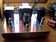
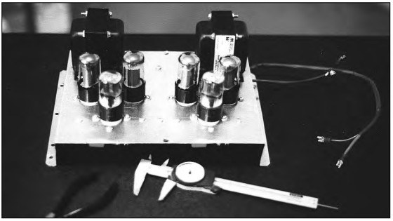
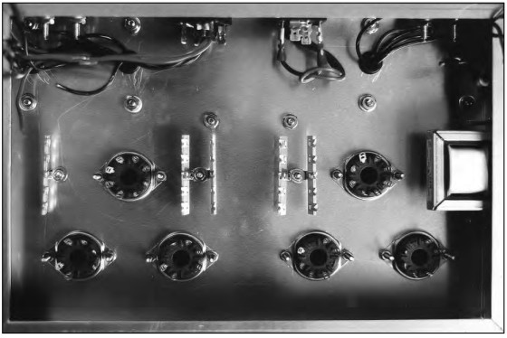
Try to set up the chassis as illustrated in Photo 2 with the two channels in a kind of “mirror image” of each other. This simplifies most of the wiring sequences. In other words, after you install a part on the left channel, you simply go over to the right channel and repeat the process. If you assemble the chassis components in this manner, you’ll avoid making the usual mistakes that can be made when you don’t have the aid of a pictorial diagram or layout chart, such as the kind that Heathkit was famous for.
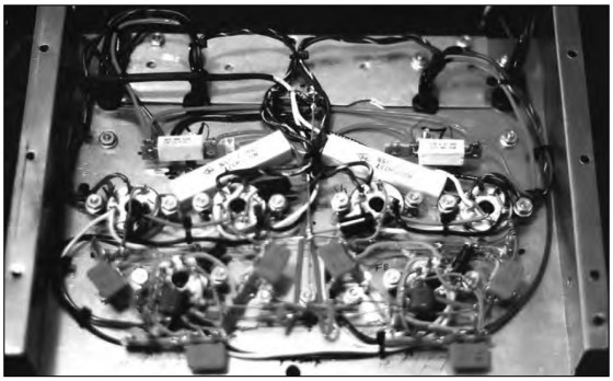
You will notice the “star” ground wires in the photo. They look like a sort of upside down “t.” This makes all of the ground connections very convenient and keeps most of the lead lengths to a minimum. Also, before connecting the leads of the resistors and capacitors, try to insulate them with heat-shrink tubing or other type of insulation. This will help reduce the chance of any shorted wiring, which can cause a lot of damage, and it also serves as a safeguard when testing the chassis for voltages (just in case you slip and misplace a test probe!). You can actually make your test probe much safer to use if you slip a piece of heat-shrink tubing over the bare metal to cover all but the very tip of it. Remember, there is some high voltage on your chassis that can be very unforgiving of mistakes!
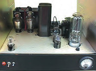
The chassis shown in the Photo 3 was a prototype and a friend of mine liked it so much he wanted me to install it in a case or enclosure. This “sub-chassis” will be in the case with his power supply and the cooling fan when completed. The final chassis box for the amplifier I’m building for myself is a Hammond #H1444-22, which is only 12 × 8 × 2″ and is perfect for this little amp. The completed unit is quite lightweight, as tube amps go, and won’t take up much room on your system rack or shelf. For us Californians who have to worry about electrical usage nowadays, this amplifier draws only about 65W of total power when going full tilt! This makes it very inexpensive to operate.
Testing Tips
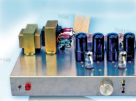
After you finish wiring the heater circuit, you can test it for proper voltage at all of the tube sockets (Photo 4). Do this with the B+ fuse removed from the holder—just for safety sake. You will find that the voltage will be higher than 12.6V because of no load on the transformer.
After you install the tubes, retest the heater voltage again. This time leave the soft-start switch, S2, “off” for a few seconds and then turn it “on.” You will notice the voltage will be about half of the normal heater rating, and when you turn the switch “on” it will slowly rise to where it should be. Check all of the heaters for that orange glow they produce to make sure they have all come on.
Switch S2 is a sure, simple way to protect your tubes from that initial surge that occurs when the resistive elements are cold. Even though the tubes in this amp aren’t really expensive, it’s a good idea to try to make them last as long as possible by treating them gently. When checking all of the other voltage readings on your amp, remember that they will probably be within 10% of the listed parameters. This is usually because of the difference in the line voltage from your utility company.
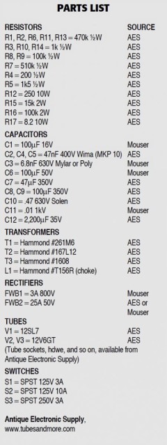
socket first! One final note about the transformers used here: If you decide to use 6V6s and 6SL7s for your amplifier, the Hammond power transformer listed will supply all of the necessary voltages because it has a 6.3V secondary included.
I am using this same transformer, #261M6, along with Hammond transformer #167L12, because I preferred to use the less expensive version of the tubes that were available from Antique Electronic Supply. So, if you use the 6.3V tubes, then you only need to purchase the single transformer. Also, change resistor R17 to 2Ω and cap C12 to 4700μF. Everything else will remain the same. Furthermore, even though this is a fairly safe and sane project with a mild B+ on the chassis, be sure to think about each move twice before probing around in your circuit. Getting zapped is never any fun.
Final Testing
Every time you test or use your new amplifier, be sure to use the proper startup sequence. Turn on S1 first, then after about ten seconds turn on S2. After the heaters have warmed up for around 20 or 30 seconds, turn on S3. Now your amp is ready to be put into service. To power down, turn off S1 first then reset S2 and S3 to off. Now you’re ready for the next time.
Remember to always have a pair of speakers or dummy resistors connected to the speaker terminals while testing your amp. Radio Shack has a good 8Ω resistor (#271-120) for this purpose. This resistor is a great way to test an amplifier if you don’t care to listen to all of the hum, pop, and other noises that are produced when you touch certain parts of your circuit with the test probes.
To test for overall frequency coverage, I used an audio-frequency generator, and this amp seems to handle the audio spectrum quite well. I really think that the way an amplifier sounds to you personally is much more important than any test results, so, after allowing it to warm up for a while, I listened to Toni Braxton’s album The Heat. This album has a great deal of punch in the midbass range, and the guitar on track #3, entitled “Spanish Guitar,” sounds very crisp and lifelike through this amplifier. I think Toni has one of the most powerful yet totally controlled voices in the music industry today.
My other test album was Jane Monheit’s Never Never Land. Engineer Tom Schick and mastering pro Gene Paul did a fantastic job of recording this young jazz artist! Her voice is very clear and natural and her phrasing is letter-perfect. The soundstage on this recording is a great way to test your new amp, or you can listen to your own favorites. Allow about 10 to 20 hours for your new amplifier to break in and settle down.
Good luck in building your version of this project. This “little amp” will serve you well for many years and the experiences you gain from constructing it can be stepping stones to other higher powered and more complex equipment in the future.
Happy listening!
www.tubesandmore.com
This article was originally published in audioXpress, December 2001.