Welcome to the most popular audioXpress DIY project we have ever published online.
Hope you enjoy this and many other articles we have available for you - and for free - at audioxpress.com
Read-on and if you feel you would like to know more, send us an email.
If you need to contact the author with technical questions, Generoso Cozza can be emailed here.
Let us know which other articles you would like to read online for free - audioXpress, Glass Audio, Audio Electronics, Speaker Builder, Audio Amateur.
But before you do, please check the other articles we have online for you on multiple categories:
Project Articles
Magazine Articles
Theory Articles
One last thing, don't forget to subscribe to our free weekly newsletter: The Audio Voice.
Just click here.
Enjoy the project.
Generoso Cozza built a Class A, single-ended hybrid power amp that combines the best of both worlds: the warm sound of tubes and the technological advances in today’s power-MOSFET devices. In the following article he explains his project.
For many years, power amplifiers used only vacuum tubes, and today’s modern amplifiers use transistors almost exclusively. Tube amplifiers operate on the same principles as transistor amplifiers, but the internal construction may be considerably different. Generally tubes are devices that operate at high voltage and supply low current. In contrast, transistors operate at low voltage, but can supply high current. Also, tube amplifiers tend to dissipate a lot of energy in the form of heat, and in general are not very efficient.
One of the most striking differences between tube and transistor amplifiers is the tube amp’s need of an output transformer. Because of the high output impedance of a tube circuit, it generally requires a transformer to properly deliver power to the loudspeaker. High-quality audio-output transformers are not only difficult to design, but tend to be large, heavy, and expensive. On the other hand, a transistor amp does not require an output transformer, and therefore tends to be more efficient, smaller, and less in need of periodic replacement.
Many people believe that the sonic quality of tube amplifiers can be both superior and possessed of a unique character. What is certain is that there are sonic differences between tube and transistor amps. I sincerely appreciate both worlds, and have had the opportunity to hear wonderfully sounding systems using both technologies.
Combined Operation
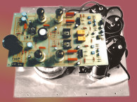
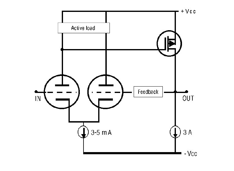
My intention in designing this hybrid amplifier (Figure 1) was to combine the best attributes of both tube and transistor technologies. Tubes offer full and faithful sound reproduction, rich detail, brilliant clarity, and accurate tracking of complex waveforms. They are also better at reproducing deep bass and extended, sweet, natural highs. Transistors are able to drive even difficult speakers while providing authoritative bass performance.
In the hybrid amplifier, the magical midrange, the soundstage size, the air and overall musicality of a tube input stage passes directly to a low-distortion solid-state output stage that retains much of the good tube qualities, yet provides a better interface to modern loudspeakers.
The Hybrid Circuit
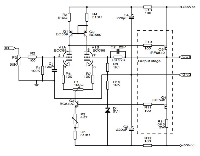
The circuit (Figure 2) is a simple design that incorporates interesting ideas such as Erno Borbely’s low-voltage tube operation and Reinhard Hoffmann’s Zen output stage with differential power supply.
This hybrid amplifier is a two-stage, DC-coupled, single-ended Class A amp, capable of delivering around 30 W in an 8-Ω load, or 15 W in a 4-Ω load. You can easily increase the output power by paralleling more output MOSFET devices with its associated current source. Such parallel devices will increase the damping factor and lower the dependence on the load impedance.
A stereo amplifier with two output MOSFET devices per channel will provide more than 50+50W of pure Class A usable power to 6–8-Ω loads. Due to its Class A operation, under such conditions the stereo amplifier will dissipate more than 300 W, so you must use appropriate heatsinks (with at least a thermal resistance of 0.2°C/W) and a suitable well-ventilated enclosure.
The input stage is based on a 6DJ8/ECC88 dual-triode tube in a differential-amplifier configuration. I selected the 6DJ8 for its linearity and good operation at a 35–40-V anode voltage. For the 6DJ8/6922/ECC88/E88CC, mu is constant within 20% from 0.4 mA to at least 6mA, and the trend continues to flatten to 15 mA. I chose an operating current of 3–5 mA for each half of the stage, and a plate voltage of 35–40 V to keep the dissipation well below the rated value of 1.8 W. You can achieve almost all the 6DJ8’s virtues at 5 mA or lower.
The cathode current is supplied by constant-current source Q3, while Q1 and Q2 form an active load or current mirror. The active load forces the anode/cathode of both triode currents to be nearly equal, which provides excellent cancellation of the second-harmonic distortion, and contributes both to linearize the operation and increase the common-mode rejection and slew rate. With P3, it is possible to adjust the bias current from 1 to approximately 7 mA, and P1 controls the output offset voltage that you must adjust close to 0 V.

Output Stage
The output stage is composed of one or more P-channel MOSFETs in a single-ended, Class A, commonsource configuration similar to the Nelson Pass Zen amp (for more details see www.passlabs.com). Its drain current is supplied by constant-current source Q4, which develops a 3-A idle current using the specified value of R14. You can experiment with different values for the idle current by changing R14 in the formula Id = (Vz−Vgs)/R14 = 0.9/R14. When defining different idle currents, you must consider the maximum ratings of the MOSFET output devices. In general, the Class A stage must carry a current of at least 50% more than the load will draw.
The overall closed-loop gain of the amplifier is around 20, and it depends on the values of R8 and R9. In this way, a 1V input signal will drive the amp to full power, so the output level of a typical CD player is sufficient to drive the amp. You may calculate a different gain by using the following formula: Av = 1 + (R9/R8).
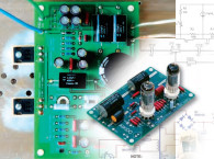
A tested PCB that you can use to build this amp is available in Ivex Win- Board format. In this PCB, the tube and the MOSFET devices are mounted on the solder side.
The Power Supply
Each channel of the hybrid amp requires a power supply capable of delivering 35+35 V DC/6A for the main amplifier, and a regulated 6.3-V DC/0.5A power supply for the tube heaters. The main amplifier power supply must include 20 A or more diode/bridge rectifiers to support the constant 3 A or greater current. Figure 3 shows the schematic of a power supply for this amp.
The Results
This hybrid amp offers a flat response over the entire audio-frequency range. Even with inefficient speakers, you can appreciate its clarity and detailed musicality, especially when a CD player is directly connected to it. With one output device, the amp provides up to 20 W with a THD under 1%, but it will work better with a second output stage in parallel. I have had the opportunity to appreciate some of the best Class A amplifiers in the market, and I believe this hybrid emanates the same fragrance and sensation of freshness when you’re listening to quality music materials. — By Generoso Cozza, audioXpress, May 2001
Editor's note: This article originally appeared in audioXpress, May 2001.