Depending on the kind of circuit used, the whole amplifier could become quite simple. Sophisticated design and the lack of an output transformer led to very good results - i.e., low distortion and wide bandwidth.
The Circuits
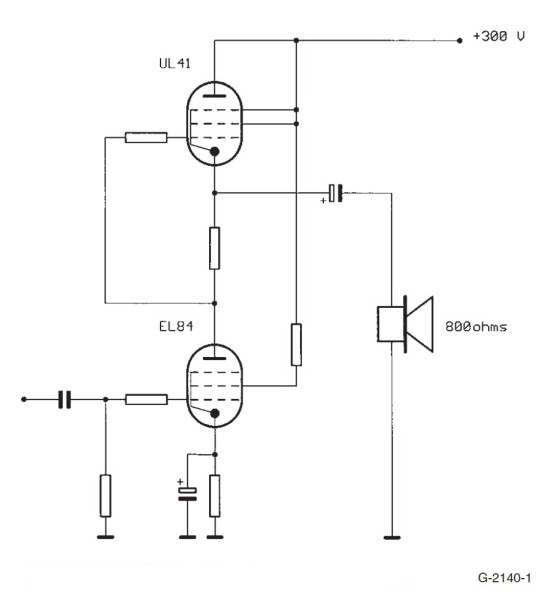
This kind of amplifier first appeared in a Philips high-end radio in 1955. This very asymmetrical circuit looks like the well-known SRPP with the upper pentode connected as a triode. The radio contained two of these amplifiers - one for the low frequencies and one for the high frequencies, feeding a total of four speakers (Fig. 1). It produced a fantastic sound.
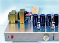
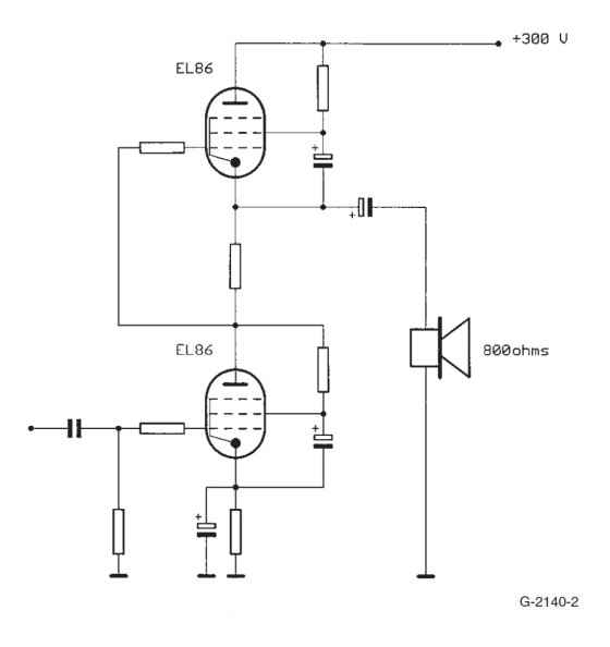
About a year later, the low-ohmic EL86/6CW5 became available; it was better suited for the task, and the circuit changed to a more symmetrical one. The screen grids were supplied via resistors and coupled to their corresponding cathodes via capacitors. Output power was about 3−4W (Fig. 2).
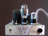
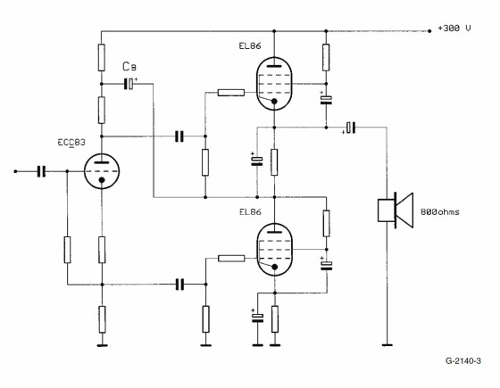
The next step was to drive the grids of both tubes separately, increasing the output power and - with the help of a bootstrap - the symmetry, too. A phase splitter delivers the out-of-phase voltages. Because the upper pentode works as a voltage follower, it needs a high input voltage. A bootstrap configuration via CB feeds the grid with the correct voltage (Fig. 3).
The Final Circuit
This section describes one of the SPP amplifiers I have built. I chose this circuit because no special parts are needed, and you can expect very good results.
The circuit is simple and even a newcomer should be able to build it with success. The design is very flexible and suitable for all low-ohmic pentodes.
There is no need for very high power supply voltages (I dislike voltages of more than 350V). To get as much power as possible the screen grids should be fed with voltages as high as the plate voltages from separate voltage sources, but this leads to a more complicated and expensive power supply. The tube manufacturer Valvo (a Philips division) developed a great idea to avoid this. In that circuit they replaced the screen grid resistors with chokes. The inductance of the chokes should be high - at least about 20H, the more the better.
Normally these chokes will be mechanically large because there is a DC current - the screen grid current - flowing through them, and therefore they need a gap, enlarging the size to get a high inductance.
The published elegant solution is to use a double choke and connect the windings in reverse so the magnetic effect of the DC currents is cancelled out. Now no gap is necessary, the choke dimensions may be smaller, and you have only one part. I used a simple small toroidal mains transformer with two identical high-voltage windings (i.e., 115V/115V) for this task. The quality is sufficient.
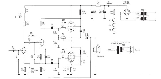
As mentioned previously, the upper pentode V3 acts as a voltage follower with a little less than unity gain and therefore needs a very high control voltage at the grid. A normal-connected phase splitter cannot deliver such a high voltage, but with the help of positive feedback (bootstrap) from the screen grid, the problem is solved by carrying high DC voltage and the output signal to the plate resistor R8 of the phase splitter tube. Without negative feedback significant distortion occurs long before full output power is reached. A NFB path from the output to the cathode of the first triode system via resistor R15 keeps distortion low. The value of R15 influences input sensitivity.
 With a value of 47k the input voltage for full power output is 1.6V. A higher value increases the input sensitivity, but distortion will also increase. Symmetry is adjusted with potentiometer P1 until you have about half of the supply voltage at the cathode of V3. A better way to adjust symmetry is watching the output voltage at full power with an oscilloscope until the signal doesn’t clip only at one side.
The recommended load for an amplifier with these tubes is 800Ω. Nowadays speakers with this impedance are scarce. But you can use normal speakers with impedances of 4−8Ω if you use an audio line matching transformer, which is available in very good qualities for only a fraction of the money you must spend for tube audio transformers.
The low turn ratio and the low impedances yield a wide bandwidth and low losses. You can even build such a transformer yourself.
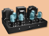
Output power of the amplifier with the values shown in Fig. 4 is nearly 8W before clipping. Depending on the amount of NFB, the output impedance is about 100Ω, causing a good damping factor for the speaker. Distortion at 7.5W is below 0.5%. Bandwidth exceeds 100kHz.
The power supply is very simple. Because I used series-heated tubes, there is no need for an extra heater winding on the mains transformer. The transformer itself is a simple 1:1 transformer with sufficient power to feed the circuit and the heaters.
The diode D1 decouples the heater string from the filter capacitors C11 and C12, and the heaters are supplied with the unfiltered voltage from the bridge rectifier. This voltage is 230V instead of 320V at C12. With D1 the voltage drop at R17 is much lower and therefore power losses are lower.
Modification
You can easily modify the circuit - i.e., use tubes with a 6.3V heater such as 6CW5 for the output and 12AX7 for the driver stage. Only a slight change in the values of the cathode resistors R2, R6, and R14 will be necessary, and you need an additional heater winding on the mains transformer. Be careful with the value of R14, and don’t exceed the maximum plate power of V2 and V3!
You could make another modification in the driver stage by using a long tailed phase splitter, which should work fine, too. You can increase output power using higher power tubes such as the 6KG6/EL509. Paralleling output tubes will also increase output power even further.
 Tubes
TubesFor this amplifier concept I chose series-heated tubes for simplicity of the power supply. Most TV sweep pentodes are also a good choice, and there are many of them available for reasonable prices. One of the most powerful in current production by Svetlana, the EL509, will increase output power to about 30W with a load of 150−200Ω in this circuit.
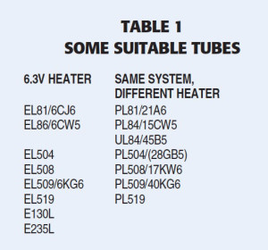
Another - perhaps the best but most expensive tube - is the E130L. And there are others. Table 1 shows a list with some recommended tubes.
References
VALVO-Handbuch Rundfunk-und Fernsehröhren 1957
VALVO-Handbuch Spezialröhren 1961
VALVO-Brief 6, Dezember 1959
VALVO-Brief 4, August 1961
Philips Service Circuit, Saturn 653/4E/3D
Philips Service Circuit, AG 9017
Winfried Knobloch, Röhrentechnik ganz modern,
Pflaum Verlag München, ISBN 3-7905-0580-3