This amplifier design strives to assign each component the role it performs best: the MOSFET used in a current stage and vacuum tubes in a voltage stage. The topology of each stage is selected for linearity, inherent local feedback, and minimum noise.
Characteristics of a MOSFET
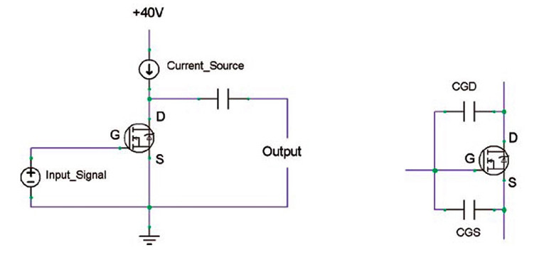
Using the MOSFET for voltage gain (Fig. 1) produces many problems for the amplifier designer. The input source is subjected to the MOSFET’s gate-to-source capacitance (CGS) and gate-to-drain capacitance (CGD), which can produce a low-pass filter, rolling off high frequencies. This problem is compounded by a phenomenon called Miller capacitance.
Small input signals at the gate produce large amplified output signals at the drain. This causes an amplified and dynamic voltage differential between the gate and drain. The input signal must charge and discharge CGD over large voltage swings with the music.
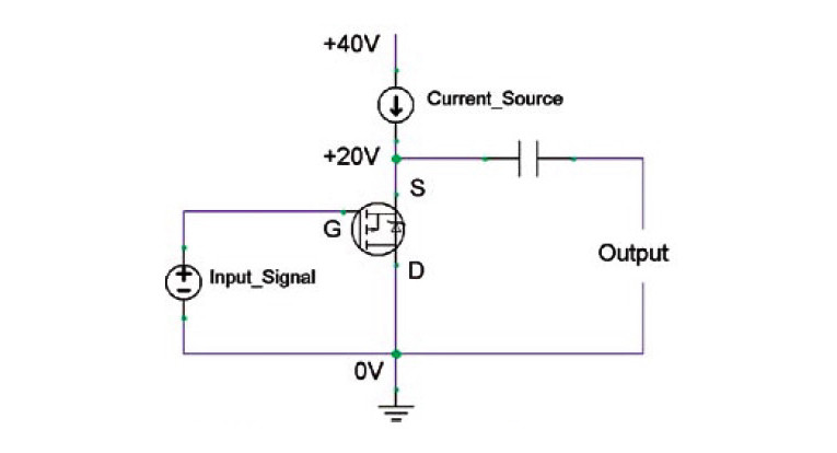
Now the input signal must charge CGS + CGD, but CGD must be charged against a much larger voltage swing. Pass addressed this issue by strengthening the input signal through a P-channel current-booster MOSFET in the Penultimate Zen. The boosted input signal overwhelms the Miller capacitance. However, you can eliminate the Miller capacitance by turning the MOSFET upside-down (i.e., using a P-channel device), in a configuration called the source follower or common drain (Fig. 2).
Configurations
The source-follower configuration is unity gain, having no voltage amplification. The source voltage tracks the gate voltage, so the gate-to-source capacitance (CGS) never sees a voltage differential. Therefore, the only capacitance the input signal must charge is the gate-to-drain capacitance (CGD). This configuration takes a high impedance input signal and converts it to a low impedance output. It employs huge amounts (nearly infinite) of inherent gate-to-source local feedback, very similar to the grid-to-plate feedback of a triode vacuum tube.
As the gate voltage increases (input signal), the source current increases (this current originates from discharging the output capacitor, adding its own current to the already present constant-current source). This causes the source voltage to drop. Because the source current depends on the source voltage, it will be lower than it would have been had the source voltage remained constant. This is what eliminates the capacitance problem, and helps tremendously with linearity.
Now, if you use an N-channel MOSFET upside-down, all the current will simply flow through the body diode. So you need a P-channel, which can be thought of as an upside-down N-channel but with the body diode pointing in the right direction.
Unfortunately, the selection of appropriate P-channel MOSFETs is limited, and this won’t make the tube-rollers happy. How about instead of turning the MOSFET upside-down, the input signal is applied upside-down? (Fig. 3).
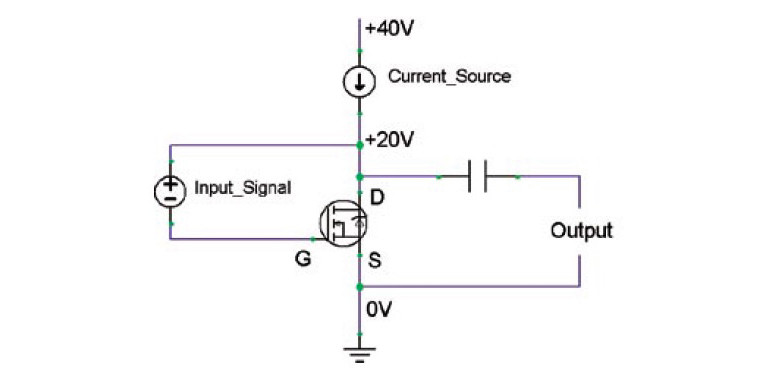
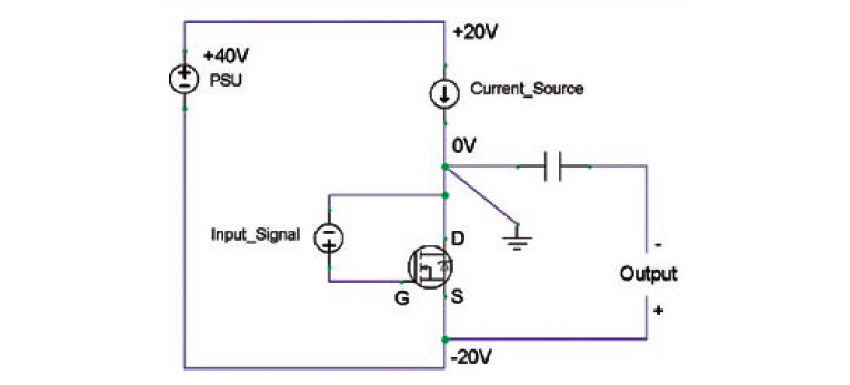
Figure 3 looks very similar to Fig. 1, with the exception that the input signal is now applied between the gate and drain. The source should follow the gate signal, but this configuration requires the input signal and MOSFET to share different grounding. One more change, and you’ll have the output stage mastered (Fig. 4).
The ground has been moved to the MOSFET’s drain, which allows it to act like a source follower. The power supply “floats” with respect to ground, and the amplified signal appears at the negative power supply rail (the MOSFET’s source). I suspect many readers aren’t going to like this unorthodox appearance.
Warning! Because the power supply floats with respect to ground, each channel must have its own independent power supply. This makes dual mono mandatory with this design. Otherwise, the channels will be fighting each other trying to float the power supply differently when music is playing.
With the MOSFET in source-follower configuration, the input capacitance becomes much less worrisome, opening up whole new worlds of component selection. I am currently using the IRFP044 (the favorite choice for the Pass Zen), but I have also tried the IFRP2907Z and incredible monster transistors such as the IXFK80N20. If it has three pins and is an N-channel, try it. The worst that can happen is it either sounds bad or becomes too hot and burns out sooner than expected (sometimes with a little puff of smoke). The rest of the amp will survive, so keep trying. A monster MOSFET won’t increase your power output. It just dissipates its heat better to the heatsink, increasing reliability and life.
How It Works
The constant-current source (covered in detail next) forces a steady current through the MOSFET. When a positive signal is applied to the gate, the MOSFET increases conductivity. The voltage across the MOSFET collapses. This draws current into the drain from load through the output capacitor. Inversely, when a negative signal is applied to the gate, the MOSFET pinches off some current. The drain voltage attempts to move further away from the source voltage. This re-routes the current from the constant-current source to the load through the coupling capacitor. The maximum output current of this amplifier is limited by how much current can be re-routed from the constant-current source.
The output capacitor needs to be large enough to pass low frequencies. I chose a Panasonic TSHA (low impedance) 10,000μF bypassed with a Solen 2.2μF polypropylene. Whether bypassing is sonically beneficial is up to fierce debate in some circles. Settle the debate for yourself. If you want the Cadillac version, skip the Panasonic and bypass capacitor and use a single Jensen 4-pole electrolytic.
Using a 50V 2A power supply, this amp will output a maximum of 25W into 8Ω. Below 8Ω, the amp will run out of current. Above 8Ω, the amp will run out of voltage. Maximum peak-to-peak output is about ±18V. You will need reasonably efficient loudspeakers (90dB/watt or better) to play loudly. This output stage prefers a loudspeaker with a flat impedance curve with no significant capacitive (negative) phase angles that correlate to low impedance dropouts. Loudspeaker matching is important. The source-follower and constant-current MOSFETs combined will dissipate 50V × 2A = 100W. Make sure to heatsink properly. This will be covered later.
Some may worry about having the output capacitor in the signal path. Nothing to be concerned about. Almost all amplifiers have coupling capacitors in the signal path. They are just hidden as the bulk capacitors in the PSU. Look at an amplifier schematic and trace the AC signal path through the amp to the loudspeaker. You’ll find the PSU filter capacitors complete the AC signal loop. In this design, there are no extra capacitors in the signal path. In this case, it happens to be more obvious.
Biasing the Mosfet
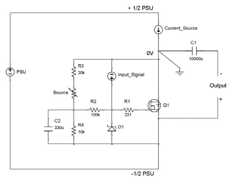
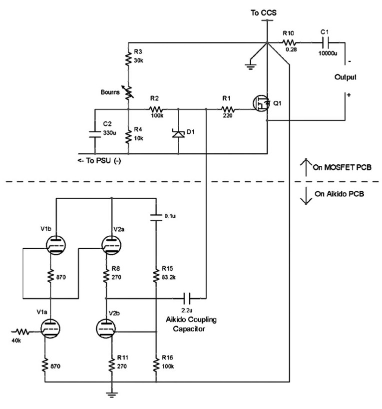
The source-follower must be biased to drop ½ PSU voltage when at idle (Fig. 5). This is performed by voltage divider R3 and R4. C2 filters and stabilizes the bias voltage. The bias voltage is buffered from the input signal by resistor R2. Resistor R1 is a “gate stopper” resistor for MOSFET Q1 to help prevent parasitic oscillations. In practice, R3 is in series with a potentiometer, so precise adjustments of Q1 are possible. I tried an op-amp servo loop here for bias control, but found a potentiometer is simpler and just as effective.
Because I’m going to use vacuum tubes for the input stage, D1 was added to clamp any high voltages and protect the MOSFET’s sensitive gate as a precaution.
The Current Source
Nelson Pass has beaten the current source to death, so I’m not going to repeat much of his work. For a detailed analysis, read his Zen version 2 article at www.passdiy.com.
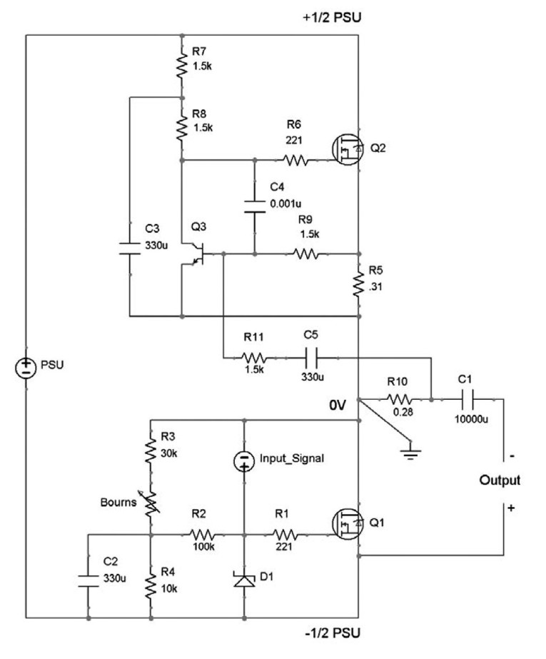
Here it is in a nutshell: the diode voltage drop (~0.6V) across signal transistor Q3 causes power MOSFET Q2 to mirror the same voltage across R5. Bias current is provided to Q3 through R7 and R8 (Q3 is a signal transistor and only needs a few milliamps). Capacitor C3 is extra noise filtering for the bias current. R6, R9, and C4 help stability. The current source output is approximately (using Ohm’s law) R5/0.6V. For a 2A current, use 0.3Ω/0.6V = 2A. Because R5 dissipates some heat (1.2W), I used two resistors in parallel to achieve the correct value.
There’s a dozen different ways to make a current source, from the arcane to the ridiculously simple. Google Gary Pimm’s battery powered CCS (arcane) or Nelson Pass Zen Variations Part 1: Zen-lightenment (ridiculously simple), where he uses a light bulb for a constant current source. I chose the CCS in Fig. 6 because it could accommodate the Pass Aleph circuit.
Components R10, R11, and C5 compose the patented Pass Aleph current source (patent #5,710,522). Pass allows the garage enthusiast (us) to use his patent. Because I built this thing in my garage with no commercial intent, I’m quite appreciative that I can use his contribution to the DIY community.
Here’s a brief explanation of the Aleph: The input signal (music) excites Q1, which causes Q1’s source to follow the music. The output signal is routed through R10 and C1. R10 acts as a current shunt and produces a small voltage proportional to the output. This signal is delivered to the base of Q3 through R11 and C5. When Q3 detects output current, it increases the output current of Q2, thereby “boosting” the CCS output a bit. Pass discovered this boost increases power output and decreases distortion.
You can use almost any N-channel MOSFET for Q2. I use the IFRP2907Z because of good junction to heatsink thermal coupling. You can even use IGBTs or other types if you get the urge. I have one running with the crazy IXFK80N20, and it works just fine. Even with the Aleph, the amp acts mostly like a constant-current load on the power supply, so the choke-filtering and capacitance multiplier still work.
The Power Supply
To get decent power from this output stage, the MOSFET needs a constant current of about 2A at 50V. The exact current and voltage is not critical, but you need to pay attention to the voltage ratings of your components. I used an Avel-Lindberg 40V + 40V toroidal transformer. I was unhappy with the bbbwwwaaannnggg it made on power-up, so I added an Ametherm NTC inrush current protection device. The NTC starts at high impedance, which charges the bulk capacitors slowly, and then drops to very low impedance as it warms up. Be sure to use a dedicated AC fuse to feed the transformer.
With constant-current power supplies, there are some tricks to help reduce noise. I’m a fan of choke-filtered power supplies, so I added a “pi filter” with choke L1. The Jantzen air-core inductors from Parts Express work very well. The 2mH choke has only 0.50Ω of DC resistance, and is a reasonable selection. The world is your oyster in this department: the Hammond 195T5 weighs 14 lbs and has 100mH. With choke filters, you can use smaller filter capacitors. I used 50,000μF surplus capacitors for the filter capacitors. Values of 10,000μF and up should work well. I didn’t specify these in the parts list. Finding these is up to you.
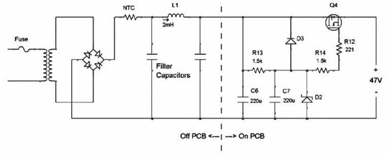
Following the pi filter is a capacitance multiplier and voltage regulator using an N-channel MOSFET (Q4) and a zener diode (D2) (Fig. 7). I use the IFRP2907Z or a TO-264 package darlington (such as the NTE2557). Capacitance multipliers work best with constant-current applications, such as this amp.
The capacitance multiplier is basically a source-follower that tracks a steady and regulated gate signal applied to Q4. Incoming voltage from the PSU rail is filtered and regulated by C6, low pass filter R13 and C7, and zener diode D2. D3 discharges C7 after the amplifier is turned off, otherwise the MOSFET’s VGD would be exceeded. R12 is a “gate stopper” for Q4, to damp the MOSFET’s gate capacitance and prevent oscillation. Save R14 for later. The effectiveness of a capacitance multiplier is determined by the filtering and regulation of the gate signal and the transconductance of Q4.
A side benefit of the capacitance multiplier is the soft-start feature. Because the gate filter circuit R13 and C7 take a few moments to charge, the PSU voltage follows this time constant. This avoids any turn-on thumps or other surges in the amplifier.
Parts selection is not critically important. I use 5mm pin 63V Panasonic FC series for C6 and C7. With a 51V zener, the output of the power supply is about 47V (the MOSFET drops 4V). If you don’t want regulation, just remove the zener entirely. If you value simplicity, skip the entire capacitance multiplier altogether and use a couple stages of passive pi filters.
My selection of the IRFP2907Z was based on good thermal junction to heatsink resistance and high transconductance (for a MOSFET). When making a choice, just make sure Q4’s voltage rating can take the peak no-load voltage of the power supply. Expect this transistor to dissipate about 12-15W (2A × 7V drop is a good estimate, depending on your transformer and zener diode selection). You can use a darlington transistor for super-high transconductance, which can be several orders of magnitude greater than their MOSFET cousins. I’ve even tried IGBT transistors.
Remember: because the output stage uses a floating power supply, you will need an independent power supply for each channel.
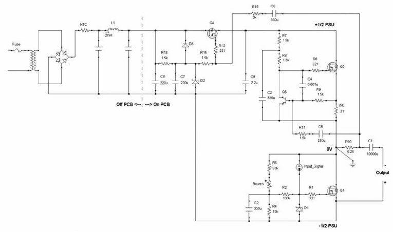
The Whole Enchilada
The entire output section is shown in Fig. 8. A few additional parts have been added: Capacitor C9 gives a bit more PSU noise filtering downstream of the regulator. Use a high-quality part. I chose the Solen 2.2μF polypropylene. R15 and C8 give the power supply a boost during large output peaks. When the output current is large, the voltage drop across R10 causes Q4’s voltage to increase a bit. This will force the power supply out of regulation (in the upwards direction), and give the amplifier a couple extra volts during peak output. R14 buffers the zener from the incoming boost signal. Just make sure you don’t violate any voltage ratings of your downstream components.
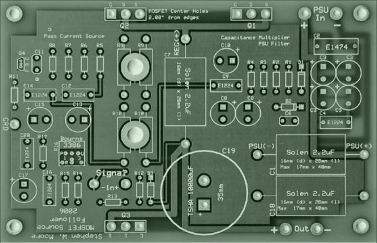
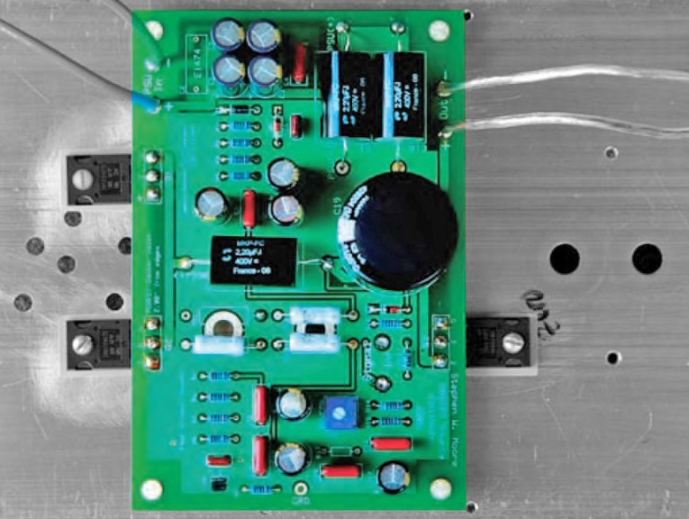
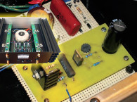
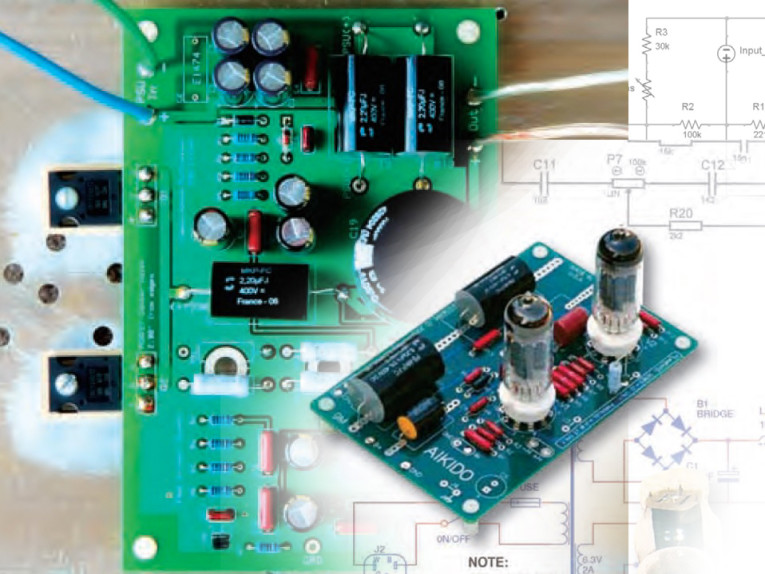
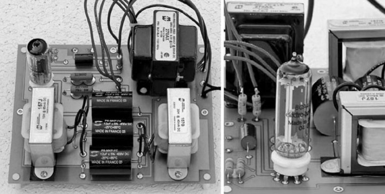
Photo 1 is a printed circuit board for the output stage and capacitance multiplier. The big circle is for the output capacitor C1. Being the first revision of this amplifier, not all of the component designations on the PCB match the text of this article. Follow good PCB layout techniques to minimize noise and parasitic oscillations. Photo 2 is a fully functional output stage on an appropriate heatsink.
I wanted the heatsink to have a maximum of 20° C rise over ambient when loaded with 120W, so it needed to be rated at 0.18° C/W. This kept the amplifier within reasonable temperatures. The capacitance multiplier was putting out about 14W (7V × 2A) and the amplifier was at 94W (47V × 2A), for a total of 108W. I used 10˝ of Aavid 65535 for each channel.
The IRPF044N has a junction-to-case thermal resistance (RθJC) of 1.3° C/W plus the case-to-sink resistance (RθCS) of 0.24° C/W for a total of 1.54° C/W. Q1 and Q2 will each dissipate 47W at idle (total of 94W). The IRFP044N is rated for a maximum power dissipation of 120W, so this seems to be within specification. The junction (inside of the transistor body) will be 1.54° C/W × 47W = 72.4° C over its ambient temperature (the heatsink). If the room is 25° C, then the heatsink will be 45° C, and the junction temperature will be 117.4° C. This is within the junction’s maximum of 175° C. The datasheet specifies a derating of 0.77W/° C when the junction is over 25° C, so the maximum power spec at 117.4° C is 48.8W. When derating is taken into account, this transistor is operating (47W at idle) at the very hair’s breadth of the derated specification (48.8W). Perfect! However, don’t expect this transistor to last a long time. Have replacements handy, especially if your room is over 25° C or the heatsinks don’t have generous access to ambient air.
In comparison, the IRFP2907Z has RθJC + RθCS of 0.73° C/W, twice the thermal conductivity of the IRFP044N. In addition, its maximum power dissipation is 310W but with a more severe derating of 2W/° C. Using an IRFP2907Z for Q2 (dissipating 47W at idle), the junction temperature is 88° C and the derated maximum power is 184W. This is plenty of headroom, and this transistor should last a very long time. You see how this game is played. It’s up to you to determine sonics.
The Gain Stage
Designing a power amplifier requires a wholistic approach. The output stage needs to be delicately coupled with the input stage for best results. To review, you should choose each component for optimal linearity and low noise. The output stage features a MOSFET, which is great for handling high current, but questionable for voltage gain. The design used the MOSFET as a source follower to maximize inherent local feedback and minimize the effects of gate capacitance. The fewer components, the easier it is to concentrate on getting each one right. The output stage has only one active device to worry about.
I played a couple tricks (capacitance multiplier and Pass Aleph current source) to earn some bonus points. The input stage will follow a similar philosophy. The vacuum tube can easily handle the required voltage swings (±20V) to drive the source follower and is well-regarded in audio circles. The triode has outstanding built-in inherent local feedback and proven linearity. It doesn’t work so well with high currents, which is why valve amplifiers have output transformers, but this won’t be a problem as an input stage. The triode features a high degree of inherent local feedback. As the grid voltage increases, the plate current also increases, causing the plate voltage to drop from where it would have been (thereby also inverting the signal).
This is negative feedback and is why triodes usually have lower gain, lower output impedance, and superior linearity when compared to pentodes, which defeat the inherent local feedback by inserting extra grids to decouple the plate current and voltage. Pentodes have much higher gain (less is lost to local feedback) and higher output impedance.
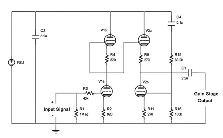
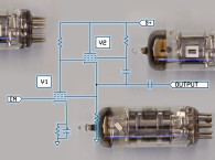
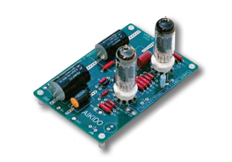
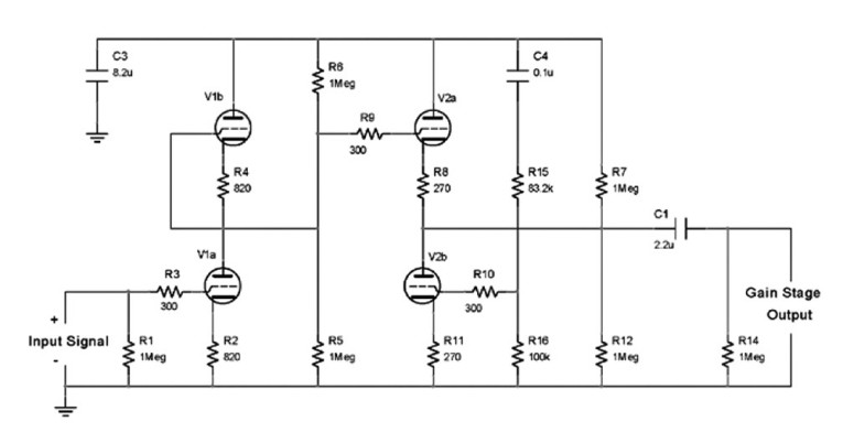
Because linearity and low noise are valued, the John Broskie Aikido input stage is an excellent choice (Fig. 9). I have named all of the component designators to match the Tube Cad Journal (TCJ) printed circuit board.
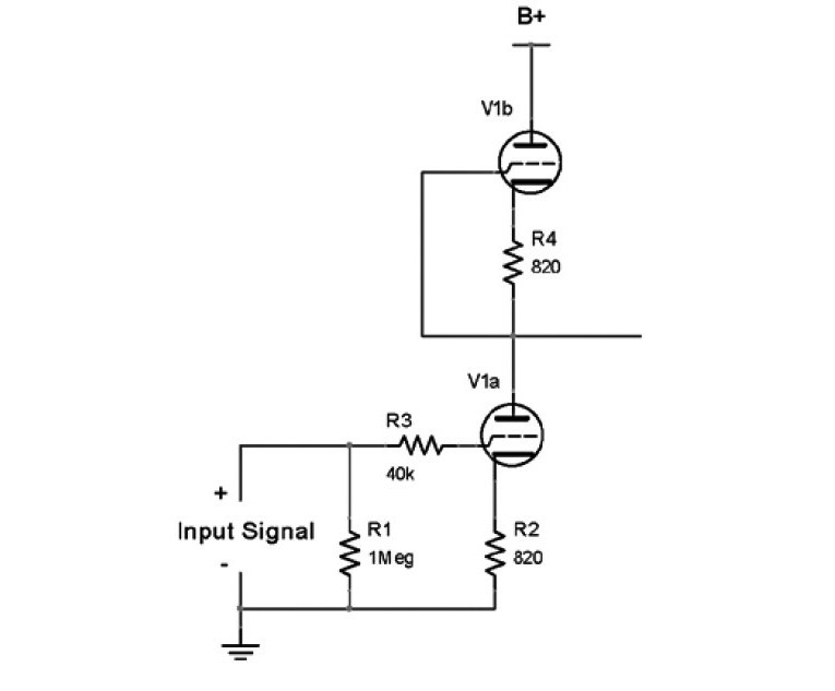
The Aikido consists of two legs that function (mostly) independently. The first leg (Fig. 10) is the voltage amplification stage. Valve V1a provides voltage amplification approximately equal to mu/2. Valve V1b is an active plate load for V1a. It loads V1a with a copy of itself, so the active load reflects the nonlinearities of the tube being loaded. It is convenient if V1a and V1b are two identical triodes packaged in a common envelope (dual triode).
If you use identical triodes, V1a and V1b will be balanced, and the first leg’s output will rest at B+/2. This also means half of any power supply noise will be seen on the output. Cathode resistors R2 and R4 should also be identical to maintain vertical symmetry. Set these depending on tube type.
I chose the Electro-Harmonix 6CG7EH, which is essentially the venerable 6SN7, but in a 9-pin package. With a 300V power supply and 330Ω cathode resistors, the tubes run at about 9mA current. I have used everything from 270Ω to 870Ω resistors with good sonic results. This tube has mu = 20, which results in a gain of about 10. The MOSFET output stage is capable of peak-to-peak ±18V (assuming 50V PSU). My signal sources are Musical Fidelity and Theta DACs, which easily output 2V p-p.
Therefore, I need a gain of only about 10 to push the output stage to full power. If you need more gain, try the 6DJ8 (750Ω cathode resistor for 6mA and gain of 14), although audiophiles will argue about sound quality of the type. For 12V heaters, try the 12AU7 (gain of 9), 12FQ7 (gain of 10), or 12AT7 (gain of 20). Others may choose to try the octal variant, using the 6SN7 (recommended).
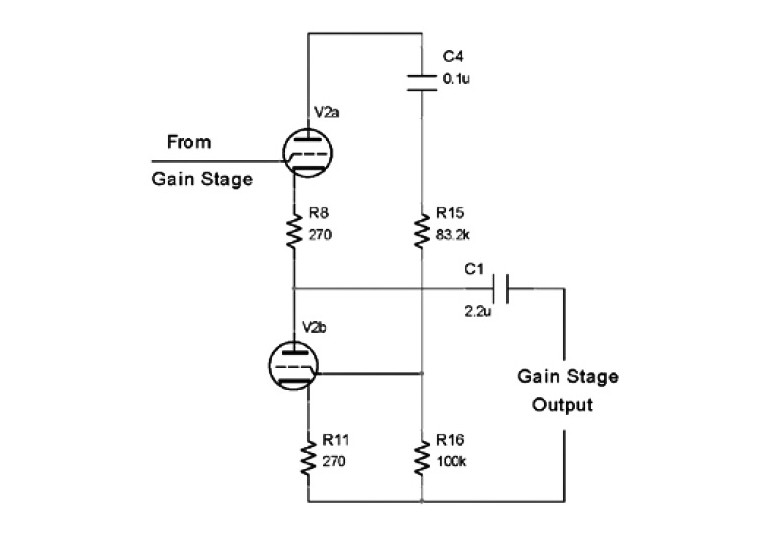
The first leg’s output is DC coupled (no coupling capacitor) into a second leg (Fig. 11), which is a unity-gain (actually, a little less than unity) cathode follower (V2a) loaded by an active cathode resistor (V2b). Again, the active load V2b loads the cathode follower V2a with a copy of itself, reflecting nonlinearities.
The cathode follower takes great advantage of the triode’s inherent degenerative local feedback (therefore, unity gain). With a twin triode, V2a and V2b will be balanced, and the output will rest at B+/2.
Here’s the Aikido magic: Any power supply noise is AC coupled through C4 to the grid of V2b. Resistor divider R15 and R16 adjust the noise injection ratio. V2b inverts the PSU noise and modulates V2a bias current, effectively canceling out any PSU noise that would have otherwise been on the output. It actually works! It is dead quiet. You can calculate the proper relationship with R15 = R16 × (mu - 2)/(mu + 2).
Cathode resistors R8 and R11 should be identical to maintain vertical symmetry between V2a and V2b. I also chose the 6CG7EH for the second leg. The important parameter is output impedance which is roughly 1/gm + R8. With 300Ω, the 6CG7EH has about 500Ω output impedance, which is low enough to drive the beefiest MOSFET in the output stage, even big TO-264 monsters.
Along with the active devices (V1, V2, and Q1), the Aikido coupling capacitor C1 is sonically important. I believe your money is best spent on active devices (tubes), before capacitors. Choose C1 with whatever budget you have left over after buying your tubes, or save C1 as an upgrade. I used a Solen 2.2μF polypropylene.
Capacitor C4 is also in the audio signal path (it influences the grid of V2b). I chose the Dayton film and foil polypropylene 0.1μF. Make sure all voltage ratings exceed your power supply’s maximum (unloaded) output. With octals (8-pin), I’d use the 6SN7. You can try a huge variety of tubes here, making sure the pinouts and heater voltages are correct. With 9-pin minis and 6V heaters, some options are 6AQ8, 6BQ7, 6DJ8, 6CG7, 6FQ7, 6GM8, 6H30... the list goes on.
Extra resistors R5, R6, R7, and R12 help keep each leg’s output centered on B+/2. These have a number of interesting advantages, including preventing damage if powering up with one socket empty or if a tube goes bad. The resistors maintain the proper B+/2 voltages, even with the heaters cold! These resistors are 1MΩ, so they have negligible effects on the circuit’s sonic performance.
You can get John Broskie’s Tube Cad Journal Aikido PCB at www.tubecad.com. You can purchase Aikido boards for both octals (8-pin) or mini (9-pin) valves.
300V B+ PSU
Be forewarned: High voltages are dangerous. The audio world needs to preserve the few brave pioneers who read about and want to build amplifiers like this. Acknowledge the dangers of working with high voltages, and do a favor to all of us: we need you. If you are unpracticed with high voltages, seek assistance.
I prefer the nature of a valve rectified, choke filtered B+ power supply. I chose the 6CA4/EZ81 rectifier because it is not grossly oversized for the application and uses a standard 6.3V heater. It is available new from Electro-Harmonix or JJ Electronics (among others). The power supply can be as sophisticated or as simple as desired. I experimented with some regulators, but found the Aikido topology is incredibly resilient to power supply issues. Heroic efforts simply aren’t
needed.
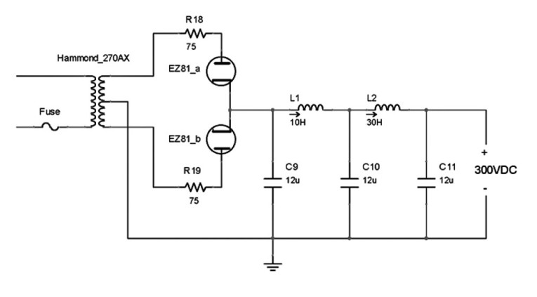
The schematic is shown in Fig. 13. The Hammond 270AX power transformer provides 50mA of 480V AC with center tap. Use a dedicated fuse for the AC feed to the power transformer. R18 and R19 are plate resistors for the rectifier. Voltage after rectification is about 325V DC (unloaded), filtered by two stages of pi filters.
Capacitors should be C9 ≥ C10 ≥ C11, or the pi filters will oscillate during the turn-on process as the capacitors charge. The first choke is 10H, rated at 65mA to handle peak currents. The second choke, being downstream and seeing smoother current, is rated at 30H and 40mA. I chose Solen 400V 12μF capacitors throughout (C9 = C10 = C11).
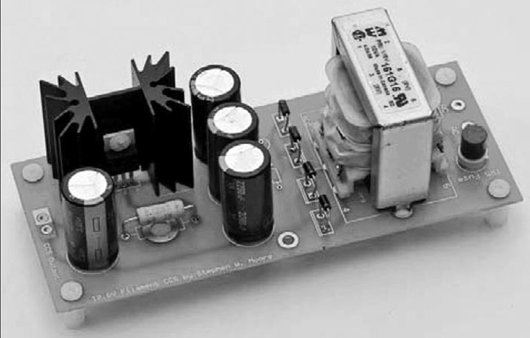
Not wanting a rat’s nest of high voltage spaghetti, I put the power supply on a printed circuit board (Photo 4). I also placed some extra solder pads for the option of replacing C9 and C10 with Mundorf 33μF Tubecap high-value electrolytics, but I’ve been quite happy with the 12μF polypropylene Solens (although, this doesn’t seem to be enough capacitance, especially when I’m accustomed to 10,000μF or more in solid-state designs).
The 6.3V secondary on the 270AX runs slightly high, so two 0.75Ω power resistors buffer the heater. This also has the benefit of slowing down the heater warmup (inrush current and thermal shock), prolonging the life of the rectifier.
This power supply has plenty of juice (40mA, limited by my selection of L2) for ambitious experimentation, and can be used for a variety of preamp designs. You can easily obtain different voltages by changing the 270AX with an alternate Hammond model.
Heater PSU
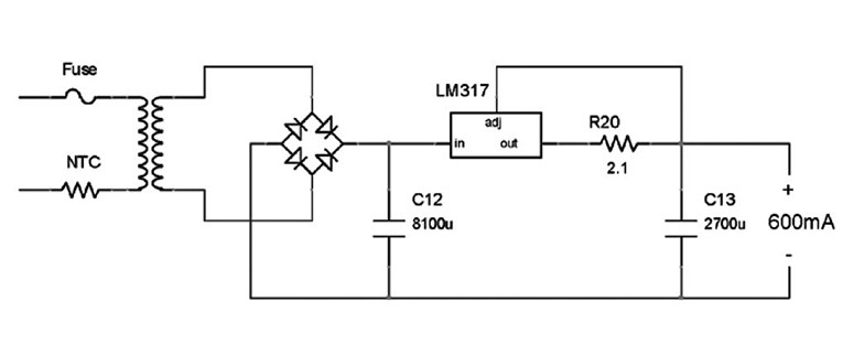
I used a separate transformer for the Aikido’s heaters. The Hammond 270AX in the B+ power supply didn’t have enough current for two 6CG7s heaters. At first, I used a 6V switching power supply brick. Unfortunately, you could hear the high frequency switching noise. Ultimately, I achieved the best sound with a DC power supply (Fig. 14). The constant-current feature is probably overkill, but I wanted to try it.
The heater supply provides 600mA at 12.6V for the two Aikido 6CG7 triodes (filaments connected in series). The LM317 is connected as a current regulator, and tries to maintain a 1.25V drop across resistor R20 (1.25V/2.1Ω = 0.6A). To compensate for the voltage drop across the LM317 and R20, the raw voltage (before the LM317) needs to be 18V.
The Hammond 161G28 provides 14V AC with the secondaries in parallel, which is rectified and filtered with capacitor C12 to about 19V. Resistor R20 dissipates 0.75W (1.25V × 0.6A), and the LM317 dissipates about 3.5W. Heatsink appropriately. As a matter of practice, I include a fuse for the transformer. I also use an NTC on all high fidelity power supply circuits that directly feed filter capacitors. The TR5 fuse is the little red button behind the transformer in Photo 5.
Assembling The Amplifier
Now you have a unity-gain, single-ended MOSFET output stage and an ultra low-noise, high-linearity valve gain stage. The output stage was designed to use the MOSFET’s inherent local degenerative feedback to eliminate the dreaded Miller capacitance, making it much easier to drive. The gain stage was engineered around triodes to get linearity, low noise, and the correct amount of gain. The triode’s output impedance can easily drive the MOSFET in this configuration.
The MOSFET output stage has an output impedance of 0.25Ω, being dominated by the 0.22Ω sense resistor for the Pass Aleph circuit. Removing the resistor and disabling the Aleph drops the output impedance to 0.1Ω. For my Triangle Acoustics Solis loudspeakers with a nominal impedance of 6Ω, that translates into a damping factor of 32 with the Aleph and 80 without. I happily trade damping factor for the benefits of Pass’s Aleph (Pass discusses the Aleph’s benefits in Zen Variations Part 4, Dec. '02, p. 16). I have also found my Solis start to sound dry and lose sound staging with too high damping factors. A side benefit of the Aleph is it increases output power. I highly recommend auditioning some of the Pass Labs amplifiers, because you’ll learn a lot from listening to the fruits of his labor.
The Aikido is coupled to the MOSFET with capacitor C1 on the Aikido PCB. With the IRFP044, you can achieve good bandwidth with a 0.47μF or larger capacitor. I used a Solen 2.2μF polypropylene, and I am happy with the result. Audiophiles can use paper-in-oil, beeswax, or pizza grease (John Broskie recommends the wet slug approach).
As a hat-tip to the Nelson Pass Zen amplifiers and the John Broskie Aikido valve stage, this amplifier has been dubbed the ZenKido. Full output power into 8Ω is 21V p-p for about 27W. For lower impedances, the output stage runs out of current. For higher impedances, the amplifier runs out of voltage. For example, maximum output into 6Ω is 16V p-p for 21W, and into 10Ω is 22V for 24W.
Some could claim that the coupling capacitors may dominate the amplifier’s sonic signature. I find it is actually a combination of V1, V2, and Q1. As Pass pointed out in his article “Practical MOSFET Testing for Audio” (Jan. '04, p. 8), the dominant sonic signature is almost always the active device. Spend more time and money considering the valves than considering C1. For Q1, the IRFP044N is a very good choice, and is also cheap. After choosing the valves, the choice of C1 becomes the next priority.
There are many parts to pay attention to: the output stage power supply, the source follower PCB, the B+ power supply, the Aikido PCB, and the heater supply. Even a “simple” amplifier is a very complex affair!
Listening
The ZenKido was designed around a low-noise, low-distortion voltage amplification stage combined with an easy-to-drive, single-ended, unity-gain, Zen-like output stage.
I found that matching between the amplifier and loudspeaker is quite important, contrary to what some noted contributors to this magazine (such as Doug Self ) have theorized. My Solis loudspeakers tend to “dry up” and lose soundstaging with highly load-invariant amplifiers. The sound becomes less engaging and more fatiguing. I’ve also noted the same effect with several other loudspeaker brands. Finding the right damping factor for your particular loudspeaker appears to be important.
This flies in the face of the notion that loudspeakers are the dominant contributors to the sonic character in the audio chain. I can’t subscribe to that theory anymore. A “straight wire with gain” may not be the best solution for you. (You could also argue this is the loudspeaker’s fault, but there is no perfect loudspeaker, just as there is no perfect amplifier.)
The Aikido gain stage imparts sophisticated and refined dynamics. The ultra low noise performance is very nice, especially with my relatively sensitive Triangle Acoustics Solis loudspeakers. The source-follower MOSFET output stage in Part 1 imparts good tonality and a lack of offensive aggressiveness. The combination of the two delivers an overall satisfying combination. The only thing this amplifier lacks is high output power, so 90dB/watt speakers (or better) will be needed to compensate. Look for flat impedance curves, which help maximize this amp’s potential, especially if the speaker lacks big capacitive phase angles that correlate with low impedance.
This amp loves a tube-friendly loudspeaker. I’ve tried this amplifier with a variety of speakers, including many DIY creations, and some from Fostex, Paradigm, Definitive Technology, Altec Lansing, and Infinity. My listening tests validate the hypothesis: tube-friendly loudspeakers are the best fit. I plowed through my music collection, listening for accuracy and soundstaging. It’s very tempting to play this amplifier loud, reveling in otherwise hidden nuances and subtleties. Solo vocalists are a joy, due to the soundstaging, profound tonality, and lack of aggressiveness.
I have found some large symphonic pieces to get lost in a muddle, presumably because the amplifier runs out of steam at loud listening levels or compression due to loudspeaker capacitive (negative) phase angles, which this amplifier has trouble dealing with.
Simply put, this amplifier likes small groupings of musicians. If you listen to a lot of contemporary vocals (Mark Knopfler, Nora Jones, Alison Krauss), jazz, blues (Jimmy Rodgers, Diana Ross), fusion (Bela Fleck), country (Johnny Cash, Randy Travis, Merle Haggard), bluegrass (Ricky Skaggs), gospel, big band, folk, new age (Enya, Enigma), or small orchestral/chamber music, then this amp is worth a try. If your bag is the classic large-format symphony, amplifier/speaker matching will be challenging.
That being said, when my system (including this amplifier) is combined appropriately with DIY Linkwitz dipole woofers, I’ve never heard the massive St. Eustache organ for Ceasar Frank’s Piece Heroique (Jean Guillou on Dorian label) replicated quite so. I’ve heard the organ live numerous times, so I have a good feel for the damp, earthy tone the recording should reveal. This was a fantastic match.
I’m enjoying the 6CG7EH (9-pin) in the Aikido. I expect the 6SN7 (octal) should also sound very good. This is a tube-roller’s paradise, and along with the Aikido coupling capacitor C1 and MOSFET Q1, there’s plenty of room for experimentation. aX
References
Elliott Sound Products, Project 15, “A Simple Capacitance Multiplier Power Supply for Class-A Amplifiers.”
http://sound.whsites.net/project15.htm
Pass DIY, “Zen Variations, Part 3: Active Supply Regulation,” (aX, Aug. ’02, p. 16), www.passdiy.com
www.stephenwmoore.com
This article was originally published in audioXpress, Oct/Nov 2007.