Design Goal
When I design using this philosophy, I must first decide what the goal is and then use the simplest possible method to obtain it. My simplest goal would be to reproduce music.
I then consider music as an emotional expression transmitted in three dimensions through a pressure modulation in the air. It comes to me encoded as a time-varying voltage of one or more channels. I wish to return this to an emotional expression, but I do not have all of the original information; by the very nature of the recording process, information is lost. I therefore do not feel guilty about dramatizing what I have to work with, to increase the emotional content in keeping with my interpretation of the original performance.
The engineering interpretation of this goal in building an amplifier involves, first, the easy stuff; that is, the bandwidth, starting with high frequency response. In the past, using a digitally synthesized signal to produce waveforms with equal peak amplitude but different time delays between tones, I established a design goal for my listening threshold as less than 5° of phase shift at 20kHz.
I like good low-frequency response. Even though very few rooms can allow a good loudspeaker to fully express itself, it is simple and inexpensive to make sure that the amplifier is not limiting the rest of the system. I have not determined a rule of thumb about the exact low-end design values, and my current rules are subject to modification as better speakers appear.
The power for an amplifier is a bit trickier. I have observed from previous designs that each amplifier has a sweet spot for the level at which it works best and the loads that it likes to see. Some amplifiers are very fussy and others are not. I have a wide assortment of loudspeakers. Some are very inefficient, others can do quite a bit with 1W. This particular amplifier design is built to be scaled. The best-sounding amplifier I ever built had an output of only one-fourth of a watt. Unfortunately, there does not seem to be a loudspeaker that would use this to produce a practical listening level.
One of the other fun tidbits to be considered is that amplifiers put out voltage, but most loudspeakers use current. The smallest version of this amplifier can produce about 15V RMS and can safely drive very low impedances. However, the current output is not symmetric. It can push several amps into the loudspeaker, but can pull back only a fraction of that. It is not what many would consider a good design, unless, of course, they actually listen to it.
The assumption that a loudspeaker requires symmetric current sources is a “plurality” that “should not be assumed without necessity.” When you apply a positive current to a loudspeaker, its cone should move inward, increasing the pressure in the box. When you release the current, the cone will move out on its own. This is, of course, a gross simplification of what is going on—just blame any problems on the speaker designer.
Distortion is another concern of amplifier design. As you can tell from the previous paragraph I am not particularly worried about harmonic distortion at high levels. The amplifier should be able to deliver low distortion of the components of the music that are important to transmit the emotion. To me this means making sure the distortion inherent in all amplifiers does not get in the way, but not to chase one measurement of distortion just because it is possible.
Settling on a circuit topology is where my biases show up. I like Class-A amplifiers. There is also floating around the audio world a superstition that amplifiers using a single output device sound better than ones that use many. The best amplifier I ever built followed this principle, but was not practical. So the basic first design cut is to scale up that amplifier.
Power Requirements
Look at the output transistor first. What is the most power a single device can yield? Power transistors are rated at 200W or more. The fine print, however, says 200W at 25° C.
As you actually put power through the transistor, it heats up. According to the data sheet, you derate it 1.14W for every degree of temperature rise. Without a heatsink, that 200W transistor is actually good for about 5W. At this experimental stage, I will not use the biggest transistor, but I will start with cheap ones so that mistakes won’t hurt as much.
The TO-220 package is the most popular case for moderate power transistors, with a wide selection of devices under a dollar. A typical transistor in that package is rated for 65W, derates at 0.52W per degree, and has a thermal resistance of 1.67° per watt. A very optimistic assumption would be an additional thermal resistance of 0.5W per degree each, for both the heatsink and mounting method.
Using a bit of algebra shows the transistor can safely operate at 27W without any safety margin. Interestingly, power transformers are rated for 115V input, and the AC line can run as high as 132V. So you should allow for a bit more voltage increasing the power dissipation.
It would be nice to assume the amplifier will run at 25° C. If placed in a cabinet, expect a temperature of 60° C. So 27W is way too high. I will use 15W as a first-try design value.
A 15W amplifier would be about 11V RMS into an 8Ω load. That would require a supply voltage of 15.5V and a supply current of 1.94A. If, for some reason, the worst-case stress were placed on the amplifier, the transistor would need to dissipate about 30W. The actual load placed on the output transistor cannot be calculated because the exact load is an unknown combination of resistance, inductance, capacitance, and back EMF. The load also has a habit of changing.
In small power transformers the three most common voltages are 12, 18, and 24V. I will use an 18V transformer, which should give a peak voltage of:
18 x 1.414 x 130 / 115 x 1.2 = 34.5V.
That is the minimum voltage the filter capacitors should be rated. The voltage to really expect depends on the transformer. I am using one rated at 18V 2A.
I have learned that when you run a loudspeaker at high power its voice coil heats up and it draws less current. In order to get more voltage from the 15W thermal limit, I will allow more voltage and less current. The current draw for my first target will average only about ½A.
The current will only be drawn when the peak AC voltage is greater than the DC voltage stored on the filter capacitors. Allowing for 5% ripple at 18V AC (25.45 peak), current will only be drawn when the AC peak voltage exceeds 24.18V. The inverse cosine of 24.18/25.45 is 18.19°. So there are only 18° of the 180 during the positive half cycle to charge the filter capacitor. My ½A through the output transistors is now a 5A load on the transformer.
The data sheet for the transformer states that at no load it produces 20.6V and 18V at 2A load. (That is why there is a 1.2 in the maximum voltage equation.) This would be modeled by a 1.3Ω internal resistance. At 5A it should lose 6.5V. So expect:
20.6 x 1.414 - 6.5 - .8 = 21.8V.
The .8 comes from the diode drop. It is larger than the .7 most folks assume because of the higher current. So for my ½A the power from the transformer should be 11W. It’s not.
There is some other bad news for the transformer. The amplifier does not have symmetrical outputs, so the load on the transformer will not be symmetric. This means when I play loud music there will be a DC bias magnetizing the core of the transformer and reducing its capacity. I could use a bigger transformer, but I will stick with my 18V 2A unit for now, using a much bigger one for a larger version of the amp.
This power supply leaves about 22V for the output transistor. In a Class-A amplifier the current always flows through the transistor. If the current is set for 600mA, the transistor will dissipate about 13W, which is close enough to allow for component and temperature variations.
I have mentioned the main filter capacitors before, but at first pass sizing them is simple, using electric field theory, not circuit theory as has been used up until now. Field theory is rarely used to design systems, because it is way too cumbersome although more accurate.
The definition of capacitance is C = Q/V. (Q is charge, or the number of electrons.) With algebra you rearrange this to be CV = Q. You then use calculus to take the first derivative:
C dV/dT + V dC/dT = dQ/dT.
Current (I) is defined as dQ/dT. Most folks assume that dC/dT is zero. Drop the term and end up with:
C dV/dT = I.
This is not a good assumption for using capacitors in audio. dC (or the change in the value of the capacitance) can occur from a change in the voltage across the capacitor, a change in the pressure surrounding the capacitor, or even movement of the capacitor. This value does not appear on manufacturers’ data sheets. Keep this in mind when a capacitor sees a large voltage swing.
Rearranging the simple form gives me:
C = I x dT/dV.
For a first try at picking a filter capacitor value, I will allow 10% ripple because there is now a greater current draw:
C = .6 x (1/60)/2.2 = 5000µF.
4700µF is the closest standard value, and I can use either 35 or 50V. A quick check of the data sheet shows that a capacitor of this size can handle ripple current of up to 1.9A. A 50V capacitor will allow me to try a higher voltage transformer, and in some suppliers’ stocks of capacitors I can only get that up to 3300µF.
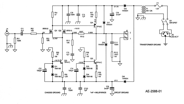
Circuit Topology
It’s time to figure out the actual amplifier (Fig. 1). Starting with the output, I can use either bipolar or MOSFET for inexpensive output devices. (If you were expecting a vacuum tube, there are lots of those designs out there.)
There are three possible ways to hook up the transistors. Common base (or gate) gives voltage gain but no current gain. Common collector (drain) gives current gain without voltage gain. There is both current and voltage gain from common emitter (source), which is a good starting place. A common-emitter amplifier with a fixed current source is the most popular gain stage in solid-state amplifiers. It is reasonably well understood and has a number of fun quirks, such as oscillation, internal parameter changes with applied power, and so on. Always an old friend.
Using a MOSFET as the output device requires driving it with a voltage source that can supply enough current to maintain the design goal bandwidth. A typical MOSFET (IRF610) has in the range of 200pF of input capacitance, and there is also Miller effect capacitance to worry about. Driving this to 100kHz requires a current of less than a few hundred microamps. The output will have a loss of less than 0.5V and meet the power goals. These are pretty good numbers.
The downside is that my selection of MOSFETs is quite limited. They are designed for industrial power handling, and devices designed for audio are rare and harder to obtain (yes, they do exist).
A bipolar transistor will require a drive current of 30mA or so. It will have an output loss of less than 0.4V, and I have a wide selection. If I wish to scale the amplifier up in size, there is a clear path of easily available larger bipolar transistors, some of which have nicely linear gain characteristics. I can add an emitter resistor to obtain some local feedback. The problem is getting enough drive current.
Using a bipolar transistor to drive a bipolar transistor output stage will require an input current of almost a milliamp. This would give me a low input impedance and loss of low frequencies, unless there are more than two stages. A MOSFET has a higher input impedance and is a voltage to current device, so providing the drive is not a problem.
If I use a differential input stage with matched MOSFETs, my higher distortion device will be in a circuit with limited gain minimizing the problem. The match between the two devices will also allow me to reduce distortion. It also makes it easy to apply global feedback.
With just two stages, one device must be of N construction and the other P. The bad news is P constructed devices don’t work as well as Ns for audio applications. The difference is worse with MOSFETs than with bipolars. To minimize the damage it makes sense to use an N channel MOSFET as the input and a PNP bipolar as the output.
A single-ended Class-A amplifier needs some current sources. It is easy to make a simple current source, such as a high voltage supply and just a resistor, or become slightly more complicated and use a transformer and high voltage supply (done that—different story), or use a solid-state current regulator. Although the regulator has more parts, it costs the least. So sometimes “plurality has a necessity.”
The usual design is a transistor, fed from a constant voltage source, dumping into a resistor. I chose to use bipolar transistors for this because their base voltage is more uniform than MOSFETs. I did a small experiment testing an LED, a power diode, and a signal diode to see how uniform their forward voltage drop was with changes in current. The signal diode had the flattest slope, and its sweet spot was 15 to 30mA. The exact voltage across the diode varies with temperature.
When using a diode voltage source for the output current source, be aware that as the output transistor heats up, its base voltage drop (Vbe) goes down and it passes more current. I will therefore assume 0.9V across the emitter resistor rather than 0.6 or 0.7V in the output current source.
Considerations
The voltage regulators formed by the series connected diodes are also bypassed by a capacitor to reduce any noise and power supply ripple. Any noise in the voltage source is amplified by the output current source.
I now have most of the basic topology of the circuit. It is pretty standard stuff to use a modest amount of global feedback at AC and full feedback at DC. I have elected not to use additional parts until I listen to the amplifier and see what each change or new part will add.
Another really important goal is to be able to actually build the amplifier. In its simplest form this amplifier can be a beginner’s project. I built this amplifier using only a drill (with bits), a soldering iron, a few screwdrivers, a pair of pliers, a small diagonal cutter, wire cutter, hot air gun, and voltmeter. I did not lay out the piece with a square and scribe; instead I used my CNC turret punch, which is a bit expensive, so you may choose to stick with the square.
If you make a mistake in building this basic amplifier, it’s probably because I forgot to tell you some important detail or you read the words I wrote, not the ones I meant. Long ago I once asked a mentor about Boltzmann’s constant. He told me it was “basic.” After about two weeks I apologized for not getting it and asked him for more information. He began by saying, “I said it’s basic, not easy.”
This is a “basic” amplifier. If you have built a few kits and choose to try a scratch build, this may be for you. It certainly helps if you have a friend who can help you with the rough spots.
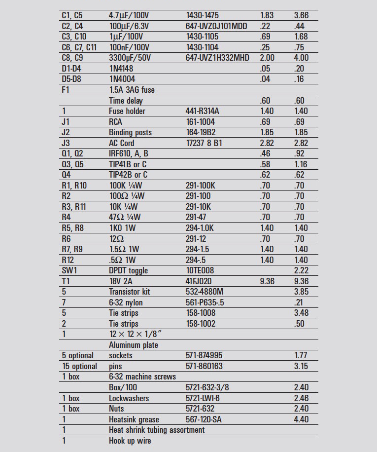
I have listed all of the parts along with the Mouser Electronics part number. Note that they do not sell some of the parts such as resistors individually. You may also wish to buy a few extra MOSFETs so you can match pairs for the input stage. I expect anyone can scrounge up some of the parts, even if it’s only a power cord from the weekly trash. If you can scrounge up the aluminum, the power cord, and some scrap wire, you should be able to build two of the amplifiers for around $100.
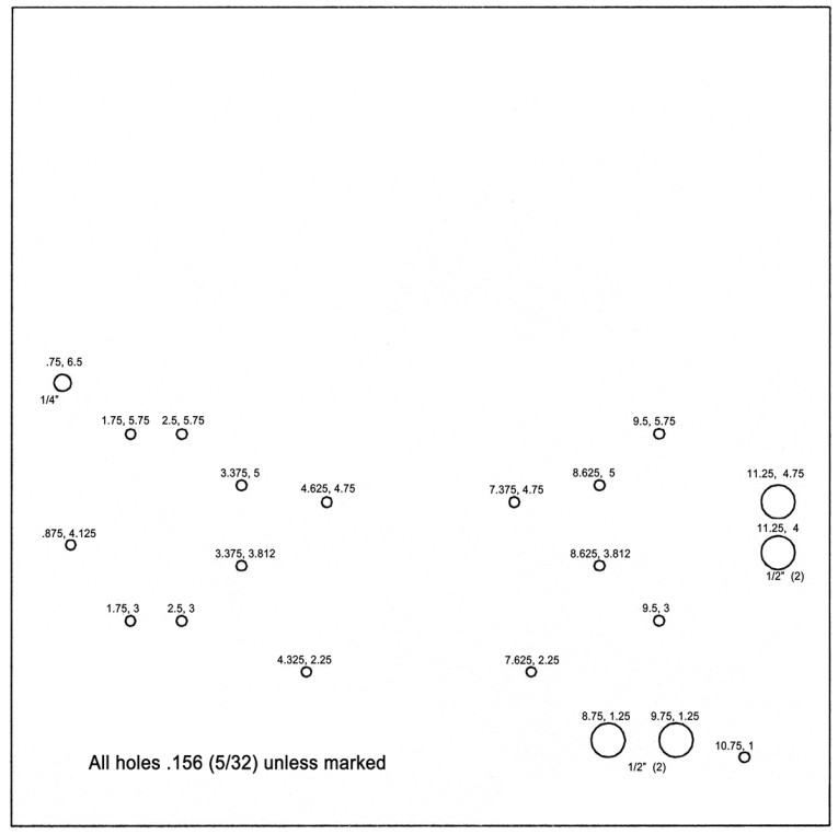
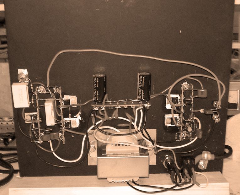
You can build the entire basic amplifier on one 12" x 12" piece of aluminum. I used 1/8" thick alloy 5052 with a temper of H32. The thickness is important to allow the heat to spread out; if you must, you can use two thinner pieces.
If you are shopping for aluminum, another choice is 6062 with just about any temper except T0. You should be able to find a piece of scrap anywhere from a junkyard to a metal shop, and, of course, you can always buy a piece on the web. There are also many other alloys of aluminum which will all work, just don’t buy already anodized aluminum.
I used terminal strips screwed to the plate to hold all of the components. That way you can easily make changes. For example, I used a TIP42C, which isn’t a great audio transistor, but it’s cheap.
You can play with others. Try an MJL4302A. You can adjust the amplifier’s sweet spot by increasing the value of R9. You can also try a higher voltage transformer. (Be sure to increase R9 also.) You can add gain stages, try all MOSFETs or bipolars. I did not use transistor sockets, but I list them in Table 1 for those interested. They aren’t intended as sockets but will work just fine.
Construction
To begin, lay out your piece of metal. You should use a 12" adjustable square. Set the ruler to one of the dimensions shown on the drawing (Fig. 2), place the edge of the square firmly against the metal just above where you want your finished scribed mark. Then place the scriber (which in many models comes stored in the handle) in the notch in the end of the ruler, and pull the tool to you, while keeping the scribe in the notch. This will allow you to place a line within .005" with just a bit of practice. When you extend the ruler more than 6", start from the opposite edge except when doing a matching hole (for example, you should measure the two holes that mount the transformer from the same edge).
Scribe all of your lines before using a punch to leave a starting dimple for your drill. If you are careful and have a sharp punch, you can feel the intersection of the scribed lines and precisely punch an indent exactly where you want it. Machinists actually have three sharp tools. The scribe, which is used only to make scratches, has a very fine tip that would be damaged if struck. A prick punch is almost the same as a center punch except the tip is at a sharper angle. It is used with a light blow to make a small indent. The center punch is then used to make an indent big enough that the drill bit will not slip out.
When done this way your hole will be exactly where you want it. Of course, for normal folks nails work well, but you will need to change often as they become blunted. To make things simple I consider the side with the lines scribed on it to be the face, the other side is the back. The transformer mounts on the bottom.
Put on a pair of gloves and safety glasses, then drill all of the holes with a B\cx" drill bit. If you have trouble staying in your center punches, use a smaller bit. If you use too small a bit, the aluminum will gum it up and break it. It is a good idea to dip the drill bit in oil or even soapy water before you drill each hole.
After drilling all of the holes, you can simply go back with a larger bit to enlarge the holes. When you do this, step up gradually to the final size, checking for fit as you go. You can go from B\cx" to ¼" to C\," to ½". Check the holes for the switch, fuse holder, binding posts, and input jack as you drill. Bigger is easy, smaller is not. You may need to wiggle the drill bit in the hole to get a precise fit for some of the parts.
After all the holes are their final size, sand the aluminum before painting it. I use 120-grit sandpaper in a small electric palm sander. You can do it by hand; it doesn’t take very long. The idea is to remove most of the layer of oxide that has formed on the aluminum so the paint will stick to it. After you have removed the dull gray aluminum to reveal mostly bright aluminum, you can wipe it with a dry paper towel or one lightly dampened with solvent. Do not use water.
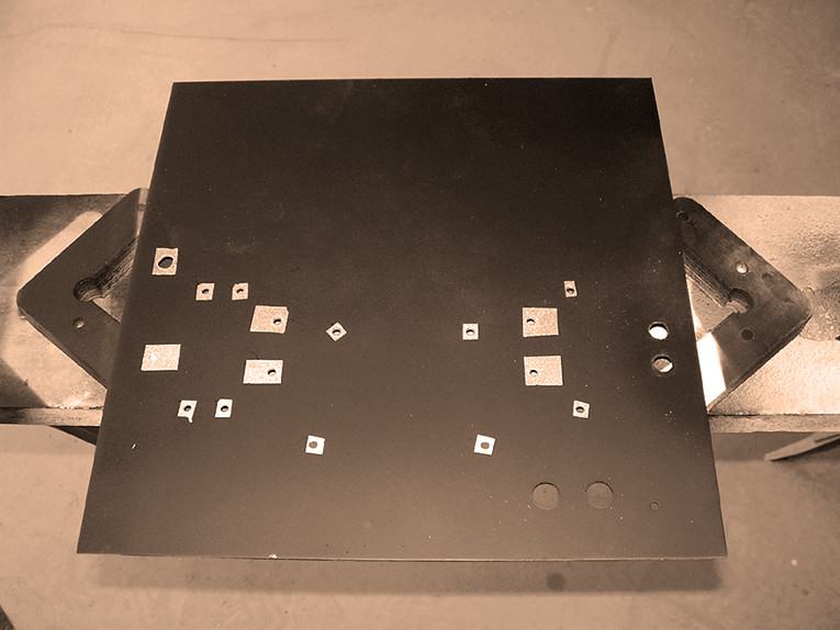
Quickly mask all of the mounting holes on both sides of the plates. I use masking tape cut into 3/8" squares. On the face side (the way it looks in Fig. 2) use ¾" pieces to mask the five transistor mounting holes. On both sides mask the ¼" hole for the input jack. It is not necessary to mask the holes for the binding posts, the fuse holder, or the switch.
The process from sanding the metal to painting it should take less than 15 minutes. I prefer the cheapest black spray paint, which is usually thin and dries fast. I spray one very light coat from all four edges on the back side, wait two minutes, flip it over on three small blocks, and paint the other (face) side. It takes me three times around all four sides with a really, really light coat to get the aluminum uniformly black. I do not want a thick coat on the face.
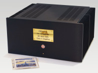
At this point there is the finish coat on the face and a protection coat on the back. After the face is almost dry (the paint I use takes 10 minutes), remove the masking tape. When the face is dry (about 1 hour), flip it over onto the blocks and put just enough paint on the back to make sure it is uniformly black. After a few minutes remove the rest of the masking tape. By taking the tape off while the paint is not completely dry, the edge of paint moves into the masked area very slightly and leaves a smooth transition. Then let the panel dry overnight. For my “case” I used just a 12" piece of 2 x 4 with a 1/8" slot cut in it off center. The plate just rests in the base and stands vertically (Photo 6).
Assembly
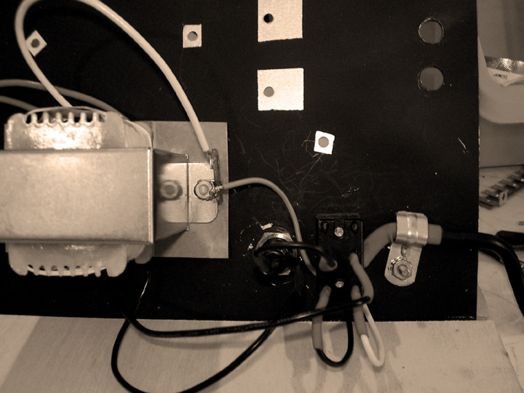
After the panel is absolutely, completely, and really dry, you can begin assembly. Start by mounting the transformer on the face side with a piece of thin cardboard underneath it, using nylon 6-32 machine screws. Mount a two-terminal strip to the right screw. Be sure the fuse is not in the fuse holder and mount it so that the terminals come up on the face side. Only the nut should be on the face side; the rubber washer should be on the bottom.
Snugly tighten the nut. If you overtighten it, you will break the fuse holder. If it is too loose the fuse holder will spin when you try to change the fuse. If you want to cheat, use a drop of super glue. Next mount the switch, again with terminals to the face side. If you use two nuts on the switch, tighten it from the face side to get a trim appearance on the back. The power cord should be clamped firmly in place.
I leave about 4" of the three conductors exposed from the outer jacket of the power cord. The green wire is connected to the grounded terminal attached to the power transformer. No heat-shrink tubing is needed here. This makes a safety ground without introducing extra noise into the audio heatsink-ground plane. You can use the other isolated terminal to store the white center tap lead from the transformer.
Place a piece of heat-shrink tubing over the black (or brown) and white (or blue) wires of the power cord. Then hold the tubing away from the ends as you solder the leads to the switch terminals closest to the edge of the switch, one wire to each side. Black or brown—depending on the power cord you have—goes closest to the transformer. From the center terminal of the switch on the side that the black wire is connected to, attach a wire that also goes to the rear terminal of the fuse holder. Do not forget the heat-shrink tubing!
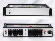
The two black transformer wires are now ready to be connected, again with the tubing on the wires—one goes to the open terminal on the switch and the other goes to the fuse holder’s terminal closest to the panel. Check to be sure your solder joints are shiny and firmly melted to both the wire and its terminal before you slide the heat-shrink tubing over the exposed metal. You can use a hot-air gun, a hair dryer, a match, or a lighter to heat up the tubing until it shrinks firmly in place. Now wrap everything with electrical tape so that you are sure no metal is visible. This is the only place you have enough voltage to hurt you (Photo 1).
You can now put in the fuse. This is a good time to check your work.
Testing
If you have the parts, you can build an AC test jig, which is simply an AC line cord, an outlet, and a 60W light bulb. Wire the ground and neutral (green and white) from the cord to the outlet. The hot (black) from the cord goes to the light bulb and the other light bulb lead goes to the outlet. Be sure to build this device using standard electrical box parts and strain reliefs. To test this device, plug a lamp into it and the device into the wall. When you turn on the lamp, it should light as well as your test jig’s 60W light bulb.
If you are brave, you can just plug your amp straight in; either way you should measure about 21V AC on the two red wires. If you don’t, try turning on the power switch. Now be sure to unplug it before proceeding.
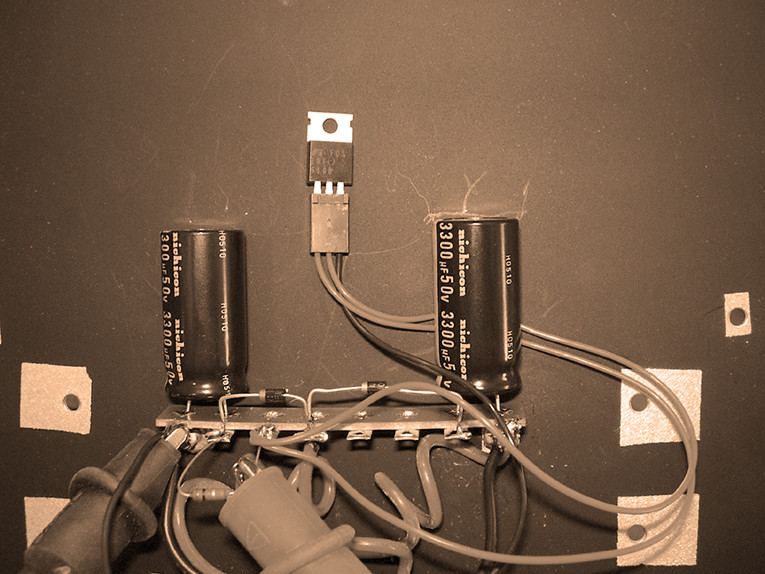
The next step is to mount the terminal strip above the transformer that holds the power-supply capacitors. You will now find out whether you put the holes in the right place. Push the steel machine screws in from the bottom. They are a tight fit going through the mounting feet of the terminal strip. Use a lock washer and nut on the face side. These screws should be fairly tight.
I mount the capacitors to the hole in the strip where it is riveted to the insulator. This is not the normal method, but it gives me a good fit and keeps the capacitor close to the ground plane. Connect the left capacitor so that its stripe showing the negative lead is connected to the grounded terminal. The capacitor on the right has the positive lead grounded.
Connect the diodes using one of the center terminals for both and the other end of each going to the capacitors. Both diode bands should be on the left side. Connect the transformer leads and a jumper between the two grounded terminals. I don’t want to just trust the mechanical connection to the ground plane. After you have this hooked up, you should test your work.
Plug the amp back in. If you are using a test box, you may notice a brief bit of light as the capacitors charge. I didn’t. Now quickly unplug the amp. Because the capacitors have no load, they will hold a charge for a while.
You have a good chance now to be sure you didn’t wire anything backward without risking an explosion. (Capacitors wired backward can explode!) You should measure about 28V on each capacitor. Be sure that positive is actually positive on both. If you have reached this point, you should have made at least one mistake by now and have figured out a way to hide it or fix it!
The next step is an option to make a temporary circuit to sort the MOSFETs. I connected one of the 1K0 1W resistors to the power-supply terminal strip and connected this to a .1" spaced triple socket. Pins 1 and 2 went to the resistor, which I then connected to the positive supply. Pin 3 went to ground. I then measured the voltage between 1 and 3.
Without a MOSFET in the socket it was about 28V. Inserting a MOSFET dropped it to 2.78V for four of them and 2.79V for five of them. One of the ten I bought measured 2.77V. This gave me four matched sets and reassured me that the MOSFETs were well-made.
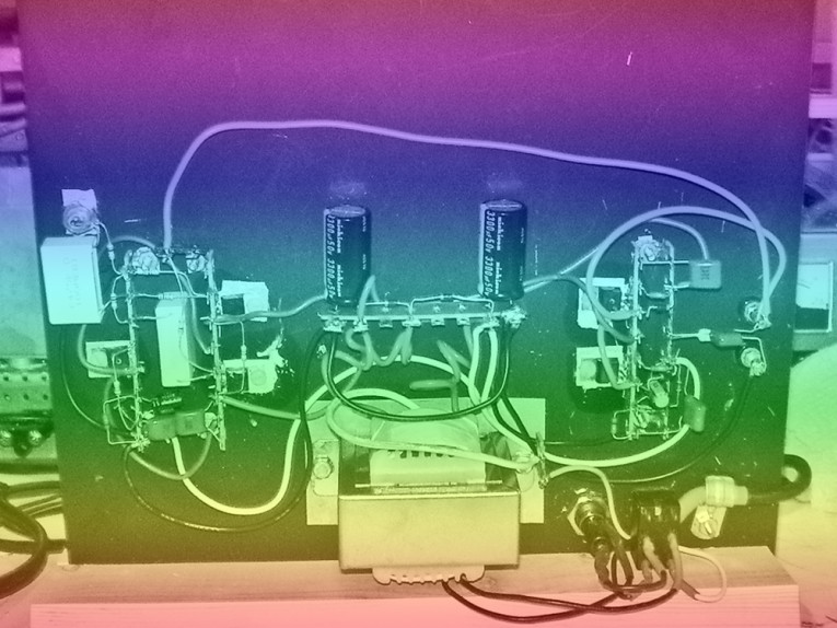
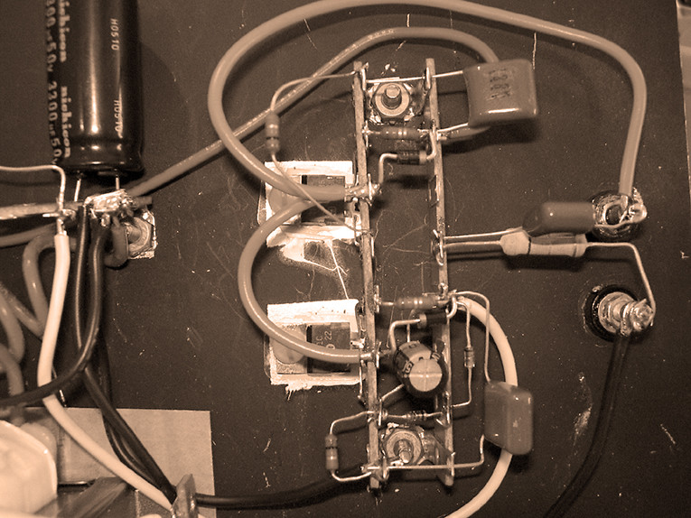
Next, assemble the output stage. Mount two terminal strips with a gap between them using two screws as before. Both strips mount in the same holes. I bent the leads of the TIP41C and TIP42C transistors quite severely to get them to mate to the rivets in their terminal strip. If you try to bend the leads too quickly or too severely, you may break them off. I use the old-fashioned method of mounting the transistors (Photo 5).
I put a very small amount of heatsink grease on both sides of a mica washer and then place this between the transistor and the heatsink. I put a nylon 6-32 machine screw through the assembly and tighten the nut from the back. Some folks prefer a steel screw and an insulated bushing; others use a thermal pad that does not require grease. The screw should be snug now and tightened later once the amplifier has become warm. Mount all of the parts to the terminal strips first and, then when you are sure you have it right, solder them. Use bits of wire to interconnect all of the ground terminals.
Insert the output binding posts at this stage and attach the output filter (C11 and R12) now. I used old green posts I had around and just painted them red and black. When you mount your posts be sure that the wire hole faces to the side, otherwise it will be difficult to connect your speakers later.
Once you have installed R7, R8, R9, R12, C4, C8, C10, C11, D3, D4, D9, and D10, you can fire up the amplifier again. The output voltage should be about -26V. Next turn the amp off and temporarily connect a resistor (1K 1W) between the base of Q4 and ground. Turn the amp back on.
The output voltage now should be more positive. It can be anywhere from -10 to +15V. If you are using a light bulb box, the bulb should glow. The output transistors will begin to warm up. The measurement from the base of Q5 to the negative supply should be between 1.3 and 1.4V. There should be about 0.7V across R9.
If it all works, turn it off and take out the extra resistor. If it didn’t work, start by checking to make sure you have your transistors connected correctly and the bands on the diodes are right. If you have C4 in backward, it won’t make much difference because the voltage is so low across it. However, it will eventually fail. If a resistor smokes, Q4 or Q5 may be shorted.
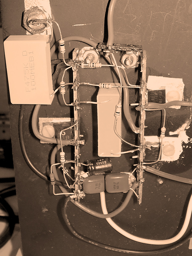
Once the output stage is working, start on the current source for the input. Install both terminal strips and mount Q3. Install R5, R6, C2, C6, C7, D1, and D2. Once these parts are connected, temporarily connect a 100Ω ¼W resistor from the positive supply to the collector of Q3. Expect to measure about 5 to 10V across this resistor. Be happy! The current source is working. Also, it’s helpful to check from the negative supply to the base of Q3; the reading should be between 1.3 and 1.9V.
Next, install the input jack and all of the passive components you can without making it hard to mount Q1 and Q2 (MOSFETs). I have never blown any of these up myself, but I am told that if you try to assemble this amplifier in the winter on a wool carpet sitting in a wool-covered easy chair while wearing silk undies, you certainly will. Handle the MOSFETs as little as possible and then hold them by the big metal tab (drain), not by the gate. The input MOSFETs do not require heatsinking but do it to make sure they are both at the same temperature. This is important to minimize DC offset at the output.
When you assemble the input, it is important that you mount R2, R3, R10, and R11 close to their transistors. If you don’t, oscillations may occur. Once you have assembled everything, take a break.
When you get back, recheck your wiring, making sure you have soldered all of the terminals (I never make this mysstake). Plug the amplifier in without a load. Measure the output voltage. If it is less than .080V, that’s great. Measure the positive and negative supplies, which should be 21V, give or take a volt or two.
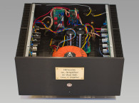
If all checks out and you have access to test equipment, look at the output with an oscilloscope or computer-based equivalent. The output should be a smooth line without bursts of ringing. Sweep the amplifier with a sine wave; you might see some distortion in the sine wave up past 50kHz. If you see bursts of ringing, be sure C11 and R12 are connected (Photo 3).
If that is not it, you can poke your finger around until you see what changes what. An extra capacitor to ground is OK at any power point. I expect that if you do see ringing the most likely problem is either an incorrect hook-up or shorting.
If you don’t have test equipment and your meter reads little DC and less than 50mV of AC, put a 1A fast blow fuse in series with an old loudspeaker and hook it up for a second or so. If all’s quiet, give the amp an input and plug the speaker back in. You should hear music. If it sounds good, it will sound really good at this point. If it doesn’t make music, remove the speaker and check all the voltages and compare them to the ones on the schematic to see whether you can find where you went wrong.
The amp will become hot to the touch, but that’s OK. If you put your finger directly over the output transistors and don’t scream much, they are fine. The power transformer will also become warm. Any capacitor heating up is a bad sign.
As you listen to your amp, you may not notice why people prefer the sound of single-ended Class-A amplifiers at first. After you listen for a couple of hours, try your old amp again. All of a sudden you will find it sounds funny! In one of those lovely psychological effects, you may not notice when something is better, but you are much quicker at noticing when something is worse.
You now have an amplifier you can both listen to and play with. If it’s occurred to you that this amplifier can be built with a PC card, or scaled up and with better parts, you are right. But then that is a different amplifier. aX
Reference
1. Dave Beckett, University of Kent at Canterbury, UK.
About the Author
Ed Simon received his B.S.E.E. at Carnegie-Mellon University. He has installed over 500 sound systems at venues including Jacob’s Field, Cleveland, Ohio; MCI Center, Washington D.C.; Museum of Modern Art Restaurants, New York; The Coliseum, Nashville, Tenn.; The Forum, Los Angeles; Fisher Cats Stadium, Manchester, New Hampshire.
This article was originally published in audioXpress, April 2006.