Condenser microphones are typically calibrated via an electrostatic actuator by the manufacturer, and then a correction factor for the appropriate field is applied to the microphone calibration. The correction factors for those calibrations are well known. Array microphones cannot be calibrated via electrostatic methods, due to the lack of a metal diaphragm, and must be calibrated using acoustic methods. This discussion will outline acoustic methods of microphone calibration, which are appropriate for both condenser microphones and array microphones. The measurements of pressure and free-field response will be described as per International Electrotechnical Commission (IEC) standards.

Frequency Response
The frequency response of a measurement microphone is determined by the sound field for which the microphone is designed. The three acoustic fields in which a measurement microphone is calibrated are free field, diffuse field, and pressure. A free field is defined as a space with no reflections, with the source being measured in line at 0° incidence to the normal of the microphone diaphragm. A diffuse field is an acoustic field in which sound has an equal probability of coming from any direction. The diffuse field response for a random incidence microphone is the average of the microphone’s response at varying angles of incidence.
A pressure microphone is flush mounted and, unlike the other two calibrations, not part of the sound field. All microphones can be used in all sound fields, but each sound field registers a different response in the microphone. This is due to the geometry being a part of (or not, in the case of the pressure response) the sound field. The plot shown in Figure 1 is all of the responses of a pressure microphone. In a typical manufacturing environment, these calibrations are carried out as a means of verifying the microphone’s design. In production, the microphones are calibrated with an electrostatic actuator. Since most microphones have a metal diaphragm, an electrical field on the diaphragm is an efficient simulation of an acoustic input. For a given model of microphone, the difference between the electrostatic actuator response and each of the other acoustic responses is a constant. This means that a “Correction Factor” from the actuator response can be used to provide the microphone’s actual field response.
The Problem
Array, Probe, and Surface microphones typically cannot be calibrated through the use of an electrostatic actuator as they do not have a metallized diaphragm (e.g., array and surface microphones) or the diaphragm is inaccessible (e.g., probe microphones). The solution in these situations is to perform acoustic field calibrations during production. Each of these field calibrations are outlined in the IEC 61094 series of standards. This article is a tutorial for performing the calibrations outlined in IEC 61094-5 (Pressure) and 61094-8 (Free Field and Random Incident). Each of these are secondary methods of calibration, meaning that a microphone calibrated in the field being tested needs to be used as a reference. The reference microphone can be calibrated by either a primary or secondary method. As this document is meant to be a tutorial, the standards should be referred to before performing these calibrations. There are many variations on these test methods, and each are well outlined in the standards. The procedures outlined in this document are one perspective: Any other method as outlined in the standard is just as valid. The base requirements, including environmental, source, fixturing, and test signals needs will be outlined here.
General Acoustic Calibration
A reference microphone calibrated via the actual field method is preferred for each of these calibrations. A standard microphone using corrected responses from actuator can be used. However, better accuracy and traceability will be attained with a microphone that was free-field calibrated against either IEC 61094-8 (Comparison/Substitution Free Field Calibration) or IEC 61094-3 (Primary Free Field Calibration by Reciprocity), a pressure microphone calibrated against IEC 61094-5 (Comparison/Substitution Pressure Calibration) or IEC 61094-2 (Primary Pressure Calibration by Reciprocity).
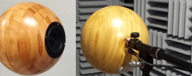
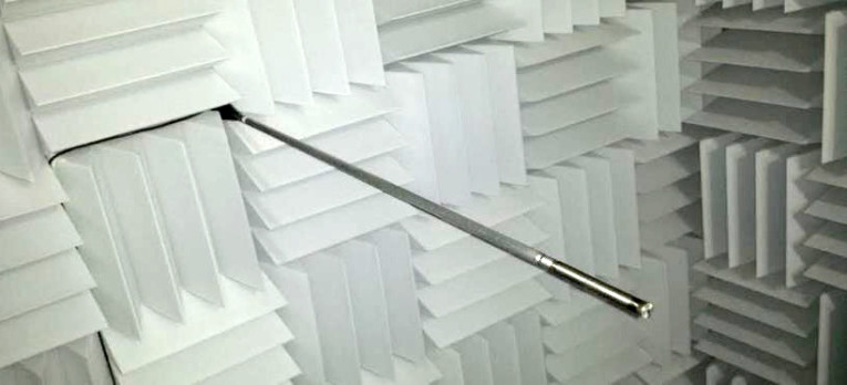
The sound source’s stability is important to the repeatability of the measurements. As the speaker is used, it will warm up, which can cause the output to change. Prior to operation, the source should be run several times to increase repeatability. Maintaining an identical sound field when the reference and test sensors are installed is extremely important for repeatability of this measurement. The source should be in the 70-to-80-dB (re 20 μPa) range throughout the frequencies of interest in order to maintain good signal-to-noise ratio (SNR). Photos 1a and 1b show images of a spherical sound source.
The spherical housing enables the speaker to deliver a more consistent signal across the frequency range. Shapes with sharp corners, including cylinders, will diffract the sound field and will cause peaks and troughs in the frequency response.
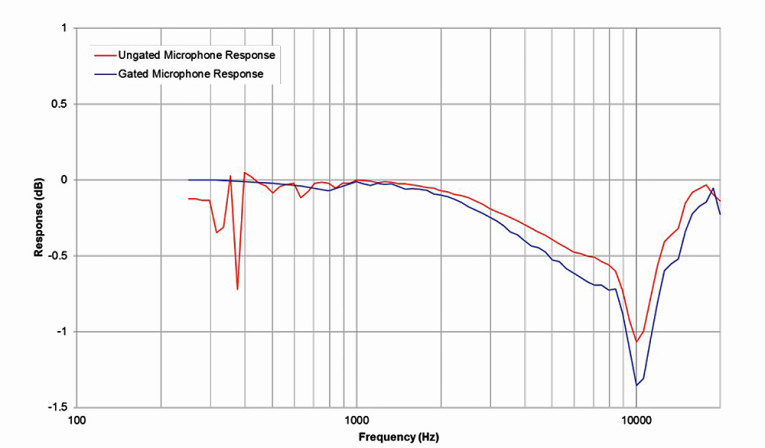
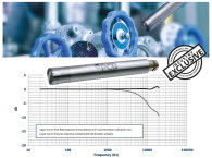
The most common signal used for calibrating is a stepped sine — a pure sinusoid is applied via a speaker, one frequency at a time, over the entire frequency range. The stepped sine helps to maintain a high SNR when the background is noisy. In a free-field test, it might be necessary to perform a time gate on the measured signal to remove any reflections from the surroundings. With a stepped sine signal, this time gate needs to be performed before any other calculations. More recently, a swept sine technique has been utilized, which allows a time gate in post processing. The full-frequency response is measured and the data is brought back into the time domain with an Inverse Fast Fourier Transform (IFFT). This time domain transformation allows for the removal of any reflections in post processing. Figure 2 shows a plot of a microphone’s frequency response, where the reflections were present at low frequency and were gated out in post processing.
Free-Field Calibration
Free-field calibration is a substitution method. Rather than a simultaneous excitation (as in a comparison method), the reference microphone samples the sound field, then the test microphone. Next, the response of the test article is calculated. For this to work, the sound field that the reference microphone and the test microphone are exposed to must be nearly identical.
Several steps are needed for this to occur during a substitution calibration. It is highly recommended that this measurement to be taken in a large room or preferably an anechoic room. The room’s noise floor should be on the order of 30 dB (re 20 μPa) or less. The ISO 3745 standard has an annex that describes the measurement qualifications of an anechoic room/free-field environment.
Temperature, humidity, and ambient pressure should all be fairly stable, as each of these can have an effect on the response of the microphones. It is advisable to track these parameters throughout calibration to compensate for any resulting changes in the sound field. Since no room is perfectly anechoic, one of the previously mentioned time-selective techniques should be employed to remove any reflection that may occur during the measurement.
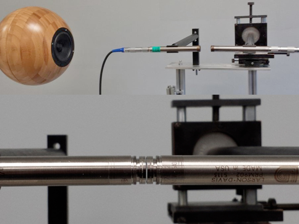
The microphone mount should be a semi-infinite rod of the same diameter as the microphone body (see Photo 2). Any imperfections in the rod (including the preamplifier connector) will result in reflections that affect the microphone’s response. Permanently mating a preamplifier with a rod and fixturing it to the wall or microphone stand will greatly increase the response’s accuracy and precision. If microphone systems have different connectors from their respective references, measures should be taken to improve the associated fixtures to maintain the fixture’s smoothness. This is because the geometry of the sound field is just as important as the field itself.
The calibration is performed by exposing the reference microphone to the sound field, taking a measurement, and then using the test microphone to measure the (ideally) identical field. The frequency response of these two measurements is computed, and the reference’s free-field response is subtracted from the paired response to define the final response of the test article.
Pressure Calibration
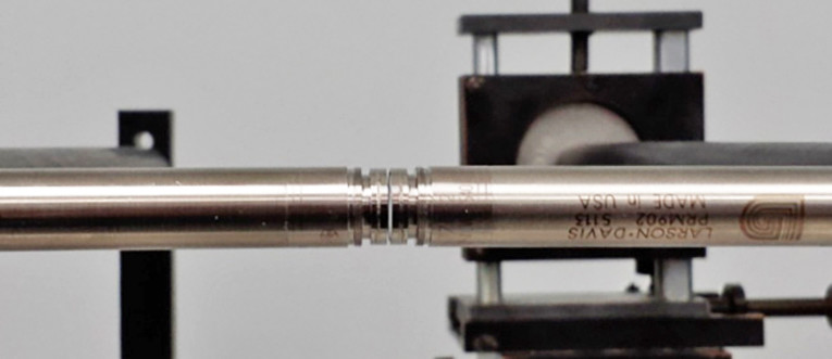
Pressure calibration can be carried out in almost any environment as long as the source output is at least 30 dB greater than the background noise. The test method is a true comparison technique, in which the diaphragm of a calibrated reference is placed in close proximity (<1 mm) to the diaphragm of the test sensor. This is to ensure that the detected sound field on both diaphragms is as identical as possible.
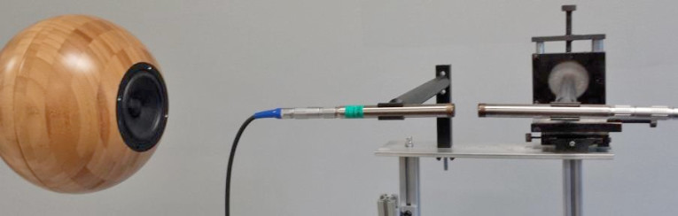
The test methodology allows for one of two possibilities. Place both microphones in a coupler facing one another with paths to enable a signal to reach the diaphragms or fixture the microphones such that the diaphragms are in close enough proximity. Photo 3 gives an example of the latter. In the event that the microphones are of different dimensions (as may be the case with a probe), a geometric corrector may be used to force the acoustic field at both sensors to be similar. The sound source should be radially symmetric about the normal of the diaphragms. This can be accomplished by revolving a source around the normal and averaging the responses, by having a radial symmetric source, or by placing the source on axis with the normal of the diaphragms (see Photo 4).
During calibration, both microphones are measured simultaneously, and the test microphone’s frequency response is computed in an identical method as was done for a free-field calibration. When asymmetric microphones are being measured, it is advisable to perform the measurement with the speaker opposite its starting location. These two responses can then be averaged to remove any dissimilarity that might occur due to the geometry of the sound field.
Closing Remarks
Since some microphones cannot be calibrated with the use of an electrostatic actuator, other calibration techniques need to be utilized. With the proper fixturing and effort, the methods outlined here can be an accurate method of calibrating any type of microphone.
Since the differences in the responses (i.e., free field, pressure, or random incident) are constant for any given model of a microphone, calibrating in one field (e.g., pressure) is a valid method of checking the other field, provided that the response corrections are known. This is a good and low-cost method where a special room is not required to perform frequency response calibration of a microphone. For more information on pressure calibration, refer to IEC 61094-5.
If a true free-field response is required, the standard requires a simulated free field for calibration. This can be done with either a large room or a true anechoic room, which can be cost prohibitive. Care needs to be taken with fixture design in order to achieve an accurate response without interference with the sound field. For more information on free-field calibration, refer to IEC 61094-8.
This document is a review of several methods of acoustically calibrating a microphone for frequency response. The basics of the calibrations were outlined here in simple language. It is by no means a definitive paper on the subject and the standards should always be referenced during calibration. VC
www.pcb.com
By Chad Walber, Carmine Salzano, Mark Nowak, and Nicholas Larratta (PCB Piezotronics, Inc.)
Adapted from the original paper published at the 22nd International Congress on Sound and Vibration held in Florence, Italy, in July 2015.
Resources
O.H. Bjor, “Calibration of microphones by comparisons,” Internoise, 2013.
IEC 61094-4, “Specifications for Working Standard Microphones,” International Electrotechnical Commission, 1995.
IEC 61094-5, “Methods for pressure calibration of working standard microphones by comparison,” International Electrotechnical Commission, 2001.
IEC 61094-8, “Methods for determining the free-field sensitivity of working standard microphones by comparison,” International Electrotechnical Commission, 2012.
This article was originally published in Voice Coil, September 2017.