
Tchaikovsky rises to a crescendo. The cannons boom through the loudspeakers. But there’s something wrong here; it’s a piano concerto, not the 1812 Overture! The “cannons” continue, out of time with the music, and now more like the continuous crackle of small arms fire. A well-placed thump on the front left corner of the amplifier and Peace breaks out.
A ghost in the machine? My Fonz of Happy Days impression? More like a dubious solder joint or a fatally wounded capacitor. This valve/MOSFET hybrid amplifier is now a fickle beast. Twenty years of hardwired mods on modified PCBs has left it an irascible veteran. This makes me reluctant to do even minor exploratory surgery for fear of causing more complications. It’s time to rebuild the amp.
Twenty years ago I designed my original Valvet amplifier around Hitachi MOSFET devices. Modern power FETs have significantly better properties enabling the use of one complementary pair per channel where previously two had been needed. This has the dual advantage of providing a reduced capacitive load for the valve driver stage and avoiding the need to match parallel pairs of devices.
Short And Sweet
A hybrid amp lets each device do what it’s good at. Valves can provide good voltage gain but are limited when it comes to current. Power MOSFETs are great at driving real-world loads, such as speakers. So here is a 50W power amp with enough gain to be fully driven by a CD player without extra amplification. Yet you can view the circuit as one valve triode, one capacitor, and a MOSFET follower. It also manages acceptable distortion performance by maximizing the linearity of the circuits rather than relying on a bandage application of negative feedback.
But I should point out that if you want an amplifier whose distortion has more noughts than a bagel factory, I suggest you shake your head sagely and move on to look for more of a “textbook” amp.
Combined Forces
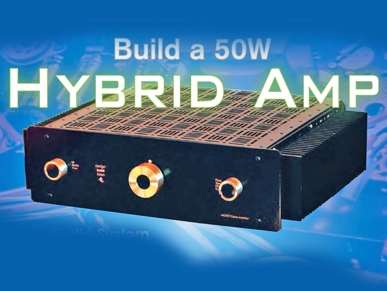
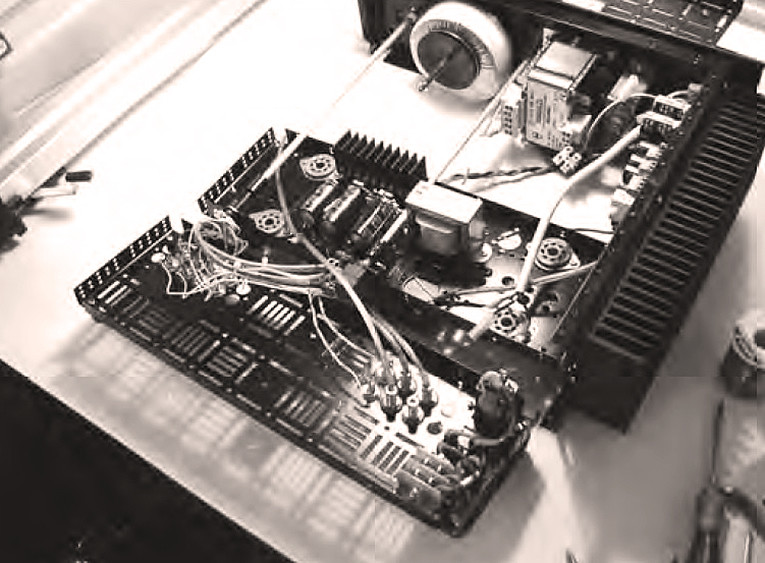
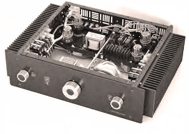
This amp (Photo 1) is a “hybrid” in many ways. There is the obvious way in which it uses both valves and MOSFETs. But it’s also a hybrid in its use of enriched Class A/B, which means it is running Class A up to a few watts. This is deliberate. The bottom bit of the transfer curve is the wart on the face of MOSFET specs that Bipolar Bullies like to point out (“MOSFETs have higher distortion than bipolar transistors”) before poking out their tongues. Running higher bias current moves you into a happier playground.
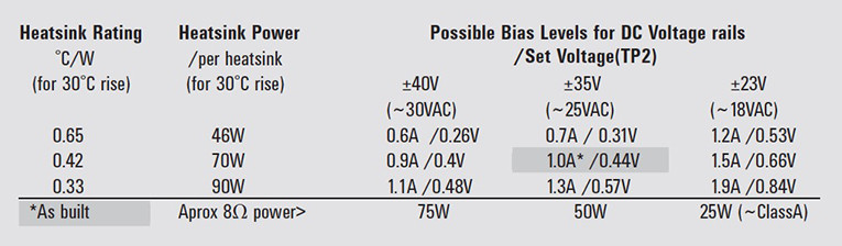
If you choose suitable heatsinks and voltage rails, you can run this design in “pure” Class A (or cooler if your budget points you that way). I have chosen the ~50W/8W Class A operating characteristics to suit my ~90dB/W speakers, and the heatsinks are simply the ones I have in stock that match my “mid”-size ezChassis chassis. Table 1 shows alternative power and bias possibilities for a number of common transformer secondary windings and three heatsink sizes. Choose the bottom right option for a “pure” Class A amp.
The Charge Of The LED Brigade
The valve “driver” stage of this amp has evolved over the years. Originally it was a triode plus cathode follower before stepping up to a SRPP (Shunt Regulator Push-Pull(1)) circuit. Then there was a significant improvement to a μ-follower(2),(3) despite my misgivings about the additional components. I had been considering adding a current source when I came across the β-follower(4) (nice to see it reinvented in aX recently(5)). This proved even more effective. What you see here is effectively a hybrid of both of these two designs using LEDs to define bias voltages.
The other major change I’ve made since my older amp is to the tube type. Power MOSFETs are relatively easy to drive, relative to big bipolar transistors, that is. They still make serious demands on the driving device, especially with their high levels of capacitance. 6DJ8/E88CCs, which were my favorite preamp tubes, are powerful (transconductance-wise) with reasonable gain, and can be low noise devices. So they seem good choices for a driver in a hybrid amplifier, as witnessed by their use in a number of commercial amps.
These are what I’ve used until now. Recently I’ve started to question how these tubes behave when called upon to swing larger voltages. In looking at common alternatives (I avoided using the sort of tube in which the entire world stock is in a locked cupboard of a locked room in a former KGB building), I decided to use the 6SN7GT because it is a linear valve with middling transconductance. Here I chose to parallel up both halves to improve its driving ability (and noise).
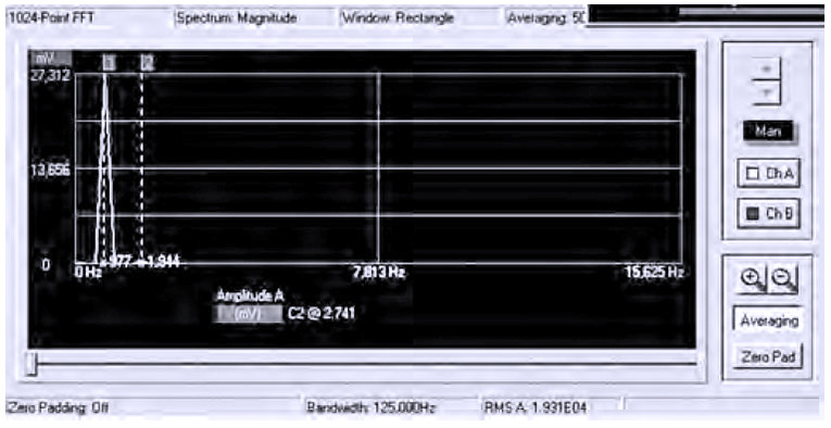
This proved to be not strictly necessary: the completed amp is 3dB down at around 500kHz (and 3Hz) and is very quiet. Gain is × 20, so can usefully be driven to clipping (56V p-p, equivalent to 50W into 8Ω) with the output of most CD players. Distortion is near the limits of my admittedly crude test gear (USB instruments DS1M12 USB oscilloscope/signal generator), but around 0.1% THD.

Campaign Plan
I configured this as an integrated amp, but you can omit the inputs/switch and replace the potentiometer with a resistor. The pot is quite a high value (100k) to help my tube phono stage; reduce this to 47k if you have a more conventional preamp. R1 and so on ensures quiet when switching inputs. I like to use a six-way switch (for my <4 inputs), giving me “free” mutes at either end of the switch travel (or in the middle to reduce crosstalk).
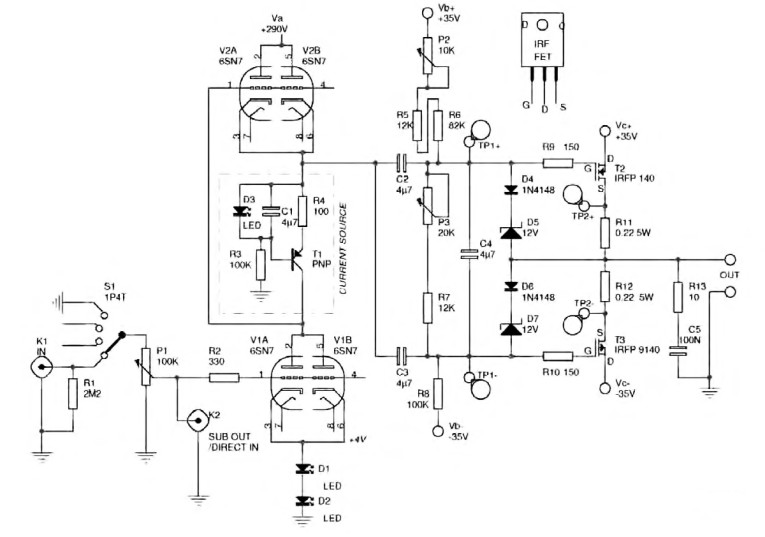
I included an input/output connection after the potentiometer to run a subwoofer and to make it easy to bypass the pot in other systems. R2 is a grid-blocking resistor, which helps avoid any RF oscillation. This is probably not necessary, but is a pragmatic choice to leave it there. Solder it as close as physically possible to the grid. R9-10 play a similar role for the MOSFETs but are essential and again must be attached directly to the gate.
The actual operation of the SRPP/μ-follower/β-follower is open to some debate, so what follows is my interpretation. You can view V1 as “simply” a triode in which V2 and the current source T1 and so on combine to act as a very high impedance load, maximizing gain and linearity. The LEDs act as a low noise biasing arrangement. V2, which also acts as a “cathode follower” to give some grunt to drive the MOSFETs, does this job superbly as this operation is enhanced by the high impedance action of the current source.
The signal is then capacitor-coupled by C2-3 to the individual MOSFETs. This is because the MOSFETs must be biased with a DC voltage (around 3.7V) to get them to operate correctly. R5-8/P2-3 form this bias network. P3 adjusts the current flowing through the MOSFETs and thus the level of “Class A” operation. P2 adjusts the balance between the devices, ensuring you can adjust for negligible DC current through the speakers.
The FETs are operated in “source follower” mode, so theoretically “track” the input with no distortion (and no voltage gain). I chose the IRFP 140/9140 pair because they are well matched for capacitance. IRP540/9540 have similar specifications but in a smaller/cheaper package (TO-220). To me the larger (TO-247) package size is potentially important because it reduces the potential for transient thermal effects. However, I did use the smaller devices to get the amp running OK.
My minimalist knife is evident at the output, where there is no inductor. Such is the advantage of a simple amplifier with no global NFB. I have left the “conventional” output filter C5/R13, which rolls off the output gently at high frequencies. I have no real evidence to say that it is necessary, similar to the grid
resistor.
Support Personnel
The diode/zener tree D4-7 protects against the MOSFETs being accidentally turned on hard. C4 performs a dual function, ensuring that both FET gates see the same voltage. It also acts in combination with the bias resistors to gently ramp up the voltage to the gates to gradually turn on the FETs (taking about 5s after the power is applied).
The rail fuses, which are open to debate, are essential when you first build the amp and may provide some longterm protection. But fuses have a nasty habit of blowing just because it’s Tuesday. If only one blows, it can lead to a nasty DC voltage at the output, so it may be wise to remove them once the amp is bedded in.
The dual LED is entirely optional and displays red when only the heaters are on and amber (both red and green halves on) when fully on.
Power Blocs
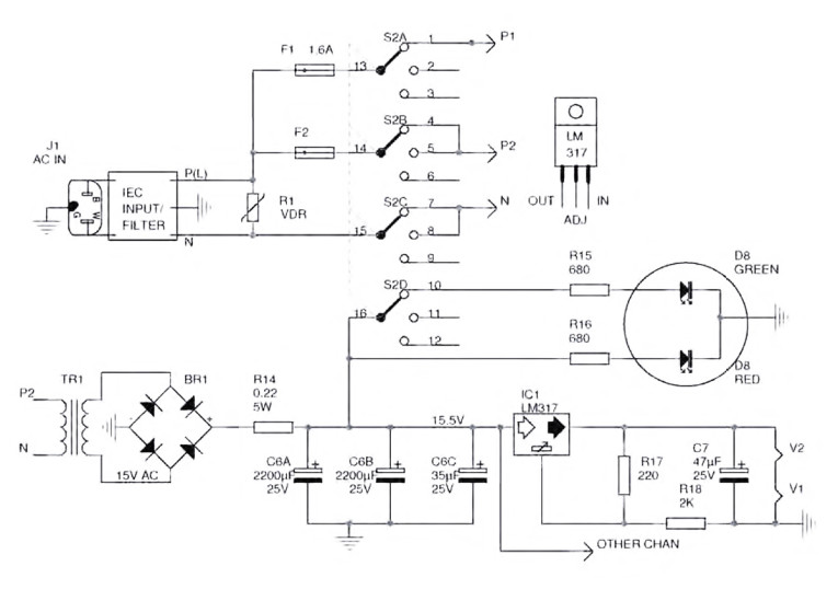
While the active part of this amp is simple, the need for three or four separate power supplies adds significantly to the complexity and cost ($800 ballpark). This isn’t entirely a bad thing as I’m a strong believer in having separate supplies for power amp driver and output stages—here they occur by default. Input: IEC 1 is a combined IEC power inlet socket and filter unit rated at 6A (230V); it is snubbed by a voltage dependent resistor to further take out voltage transients. While both of these are optional, I recommend them or at least some form of input filtering. SW2 has a “standby” position that enables the heaters to be warmed prior to turning on the HT. Here I’ve used a separate heater transformer, but if you have a combined HT/heater transformer, you may choose to switch the HT by relay, ideally with a delay mechanism.
Heater Supply: LM317 regulators provide a cheap, clean DC supply to the heaters, but because they are dissipating a couple of watts, they must be heatsinked. One of the nice aspects of 6SN7s (over 6DJ8/E88CCs) is that they can stand 200V from the heater to cathode, so there is no need to jack up the supply (or worse, limit the HT rail). However, if you are using “dual” 6SN7s as I have, with heaters in series, I suggest using the grounded heater for the lower valve. You may need to adjust the exact value of R14, depending on the “sag” of your heater transformer secondary.
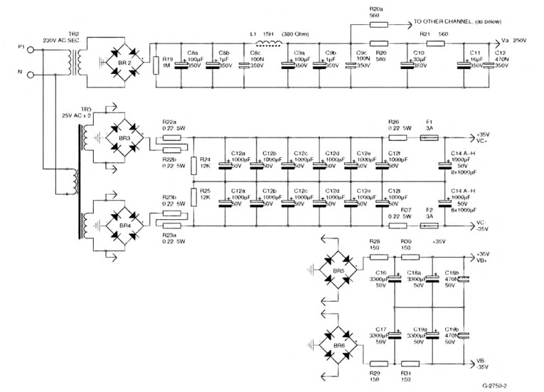
HT Supply: I’ve shown a pretty conventional supply here based on a 230V transformer secondary to give ~300V. But if you are starting from scratch, you may consider running a rail closer to 400V (possible with the 200V heater/cathode voltage limit). The actual capacitor values are pretty arbitrary, but I don’t recommend using much less than I have here. If you want to avoid the inductor, you should consider more capacitance or a regulated HT supply.
MOSFET Bias Supply: Because I wanted to keep the biasing as stable as possible, I incorporated a separate power supply for the MOSFET biasing. This avoids the potential of being disturbed by the output. I haven’t actually used a separate transformer (if you do, choose one to give slightly higher voltage rails than the main MOSFET supply), but the separate bridge rectifier alone gives good isolation. If all this seems unnecessary or expensive to you, you can attach the biasing resistors to the “main” voltage rails.
MOSFET Power Supply: Having been brought up in the 1980s low impedance school of amplifier design, I’ve now undergone somewhat of a sea change and can be caught sneaking resistors into power supplies. A small amount of resistance dramatically improves the effectiveness of the filtering. The resistor immediately after a rectifier further helps by increasing the conduction angle of the diodes even if you “lose” voltage. But you’re free to experiment without the resistors.
I chose to use banks of paralleled capacitors rather than single large value caps to give low impedance. I’d already (less scientifically) chosen these Panasonic NHG 1000μF (50V) capacitors before Paul Stamler’s helpful article(6) in aX which also uses them in parallel. I considered 10,000μF a minimum value, with money and space being the upper limit. I ended up using two 160VA transformers, which is about the minimum size I’d suggest for the bias level I used. These gave ~80W into 4Ω before clipping. To avoid blowing fuses on power-up, I used a NTC thermistor in the feed to the MOSFET power-supply transformers.
Rectifier Choice: To avoid high-frequency noise from the rectifiers, I prefer to use Schottky diodes, but failing that, fast/soft recovery ones. If this is difficult or you remain skeptical, use snubber capacitors across regular diodes. I originally planned to use a tube rectifier for the HT supply, but this limits the possible capacitance at its output (although it does provide a desirable slow HT start-up).
An Exploding Chassis
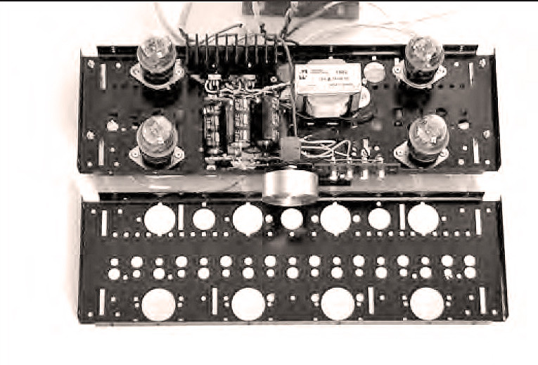
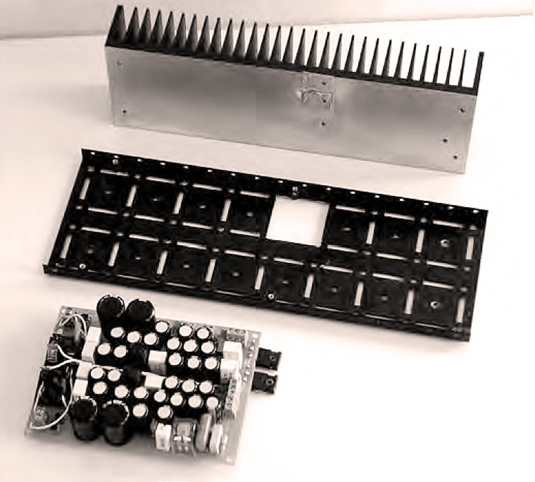
I must declare my involvement in the ezChassis used here to house the Valvet (Photo 2). This is not surprising, since I designed it after frustration with previous amplifier projects. Of course, if you’ve got the time/skills, you can build it into any old box that suits you and skip this section. Here I have used the 120mm (~5˝) high ezChassis and matching 100mm × 300mm (4˝ × 12˝) heatsinks. Part of my thinking behind ezChassis was to make it possible to remove individual panels for servicing. Many audio enthusiasts like me forever want to try out some improvement or other. This feature helped in construction because I was able to build and test it in modules before final assembly.
I haven’t provided a “step by step” construction guide here; otherwise, this article would be considerably longer. In this form this amplifier is not suitable for a novice builder (but I may yet offer a PCB-based kit in the future). I will offer a few general comments, which won’t be news to old campaigners:
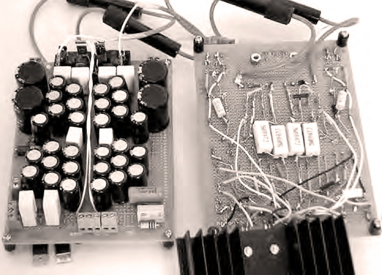
• Build and test the tube driver separately. I built mine as a hard-wired unit including the coupling capacitors on one “Tube Mounting panel” (Photo 3). I can’t pretend that I didn’t need to drill any holes, but there were very few because this panel is provided with mounting holes for octal and B9A tube bases and a raft of slots and holes which proved useful. In hindsight, I should have mounted this panel vertically (not horizontally) to support the back end of the shaft extension.
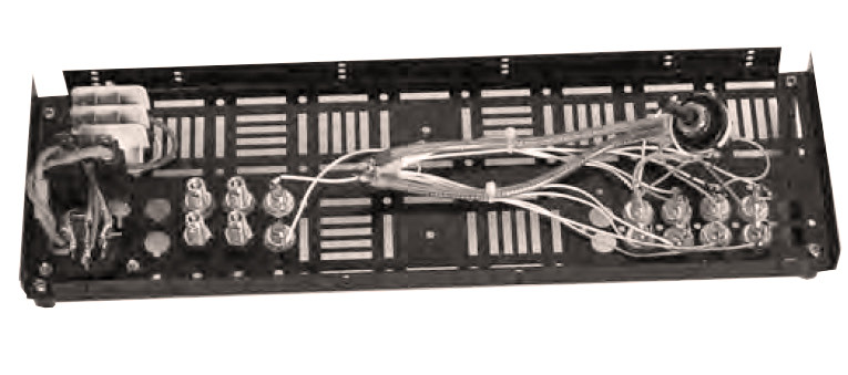
• To keep the signal path short I used shaft extensions to mount the input switching and volume pot at the back of the chassis, enabling the back panel to be built up as another module. The front end is supported by the structural panel behind the cosmetic front panel (Photo 4). I found it easiest to install all the back panel components, including handles (because the amp weighs ~35 lb) before attaching it to the other panels. Knockouts are provided for the IEC mains entry and labels (supplied with ezChassis) are used to blank off unused holes (Photo 5).
• Because the panels have baked on paint, I locally scraped paint off (under screw heads) to ensure they were earthed.
• I built the power modules on PCB “spot” board (I don’t know the “correct” name), which makes it easier to deal with wiring up all those capacitors. This board is a recent discovery for me and I’ll enthuse about it to anyone.
I assume I’m not alone in spending hours hunting unintentional joins in “stripboard” and even more time replacing the components I blew up when I missed one. This board enables you to use the small solder pads around each hole to locate the components while enabling hard wiring. Its holes are at a standard pitch that enables you to place many electronic components without drilling extra holes (Photo 6). I then mounted these boards on standoffs on the side panel with a section “knocked out” to access the heatsinks (Photo 7).
• I (re)learned a lesson when building this amp. Don’t recycle components. It’s not worth it. I spent hours trying to figure out a problem with the HT supply. It was due to some dodgy capacitors.
Test Firing
As I mentioned, I built and tested the tube stage separately (heater first then HT). Similarly I strongly suggest a stepwise approach to each channel of the power section. I tend to use a protective RCD until I’ve confirmed that all is well (keeping my finger poised on the off button while looking for trouble).
• Before placing the FETs, try the other parts of the circuit. The independence of the bias supply enables that to be tested first. Check for the 6-9V adjustment across the gates (TP1) before turning down to the minimum value (around 6V). Next check the main MOSFET power supply before installing the FETs. With any power supply, I usually flick my multimeter over to AC volts after confirming the DC value; this is a simple noise/hum check. You should get a near zero reading (though my Fluke multimeter gives more sensible results here than my “El Cheapo” meter).
• After connecting the MOSFETs (and attaching them to the heatsink), check once again that P3 is adjusted to zero before powering up. You need two multimeters (even cheap ones) at a minimum, because it’s pretty handy to be able to watch the gate voltage (TP1) at the same time as the bias voltage drop across R11-12 (TP2). There should be no voltage across these resistors when you start (the FETs are turned off).
Adjusting P3 upwards, when the gate voltage gets to around 7.2V current should start to flow through the FETs. But note that IR’s datasheets give this turn-on point a very wide 4-8V tolerance, so do this very gradually. Stop at about 150mV and watch until you are sure it’s stabilized. (You can do this without the valve driver stage or speakers connected.) This is about the minimum level of bias. I chose 0.44V (~1A) for my heatsinks. You should watch very carefully over a few hours that it’s stable (I checked on each start-up for the next few days).
• Check the DC offset across the output terminals and adjust P2 to get it near zero (I try to keep it below 50mV) before connecting speakers.
Tchaikovsky Encore
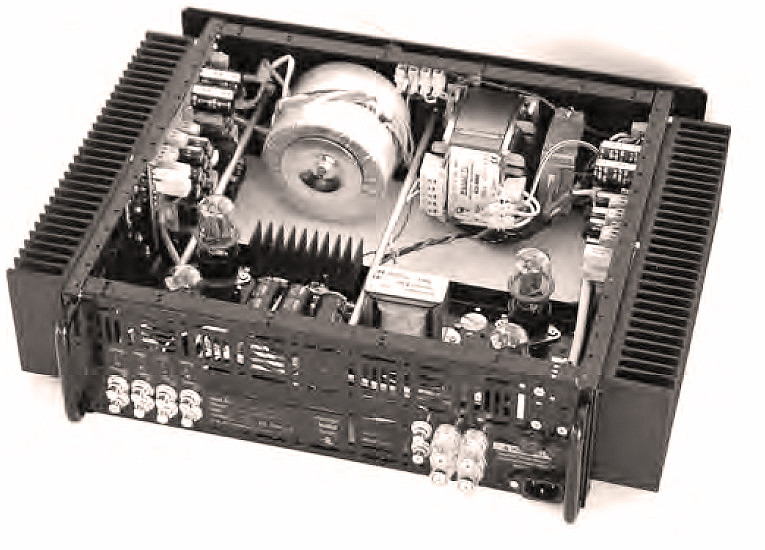
Describing the sound of your own gear is full of obvious dangers. But suffice to say its sound is somewhat “hybrid” too, having a “valve” midrange but a “transistor” bass end (if a little “softer” due to the lack of global feedback). The Valvet amp (Photo 8) proved to be a nice match for a friend’s Thor transmission line speakers, driving them comfortably. With my newly built Fostex full range driver speakers (93dB+), I’ve been caught grinning like a James Bond villain who has just perfected his Death Ray.
Conversely at home I hear musical detail I haven’t noticed before. This isn’t detail for its own sake but more the big musical picture, seeing how the parts/harmonies fit together in a coherent sense. One of the things that surprised me was how quiet the amp is. Other amps I’ve used are apparently silent, but here delicate music is audible against a dark background.
The new amp is great; it no longer makes cannon fodder of Tchaikovsky. Thanks to Alan, Richard, Julian, John, Phil, and Jean for helping me with suggestions and support for the amp and
this article.
Trademarks: “Valvet” and “ezChassis” are Trademarks of Design Build Listen Ltd. aX
References
1. “Valve PreAmplifier,” J.P. Guls, Elektor, March 1987.
2. Letter to the Editor, Christopher Paul, The Audio Amateur 4/85.
3. The Tube Preamp Cookbook, Allen Wright 1995.
4. Valve Amplifiers, Morgan Jones 2003, p. 126.
5. “Design a High Performance Valve-Based Line Amp,” Chi C. Wong, audioXpress 10/05.
6. “Capacitor Bypass: Proceed Carefully,” Paul Stamler, aX 5/05.
This article was originally published in audioXpress, March 2007.