The Bias Meter Theory
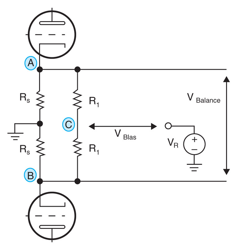
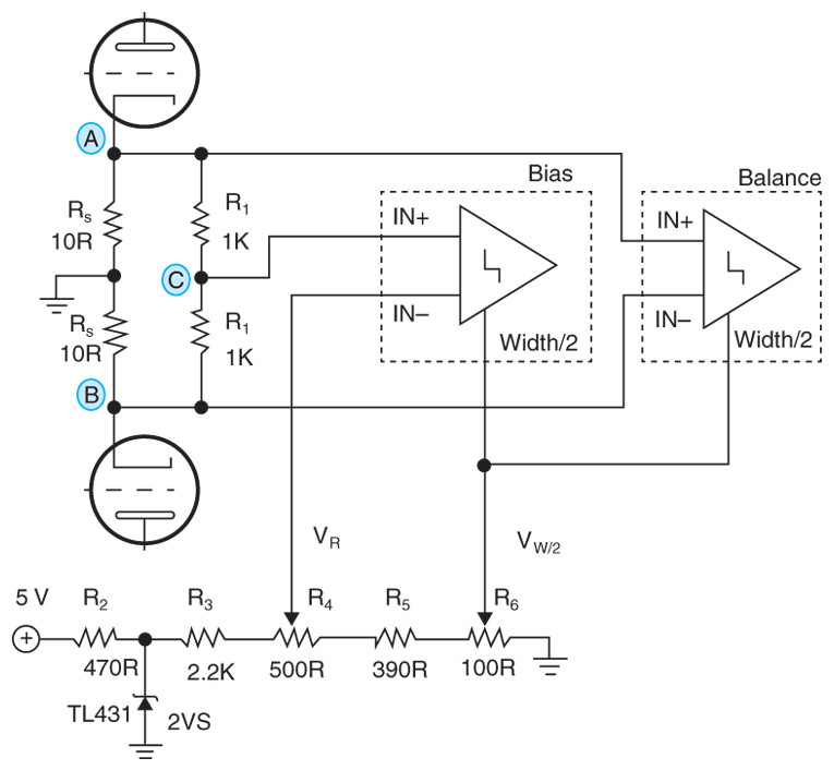
A small value sense resistor RS is connected in series with each output tube (see Figure 1). Balance is measured between points A and B. This type of balance meter configuration is fairly common. Bias is measured by averaging the voltages A and B at point C and comparing the result to a DCA reference voltage, VR. The reference voltage is set based on IO, the target bias current per tube, according to VR = IO × RS. To the best of my knowledge, this arrangement for measuring bias is unique.
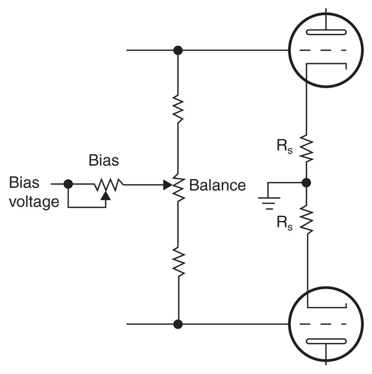
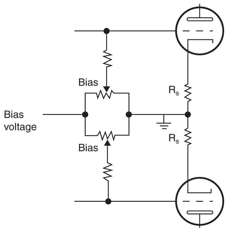
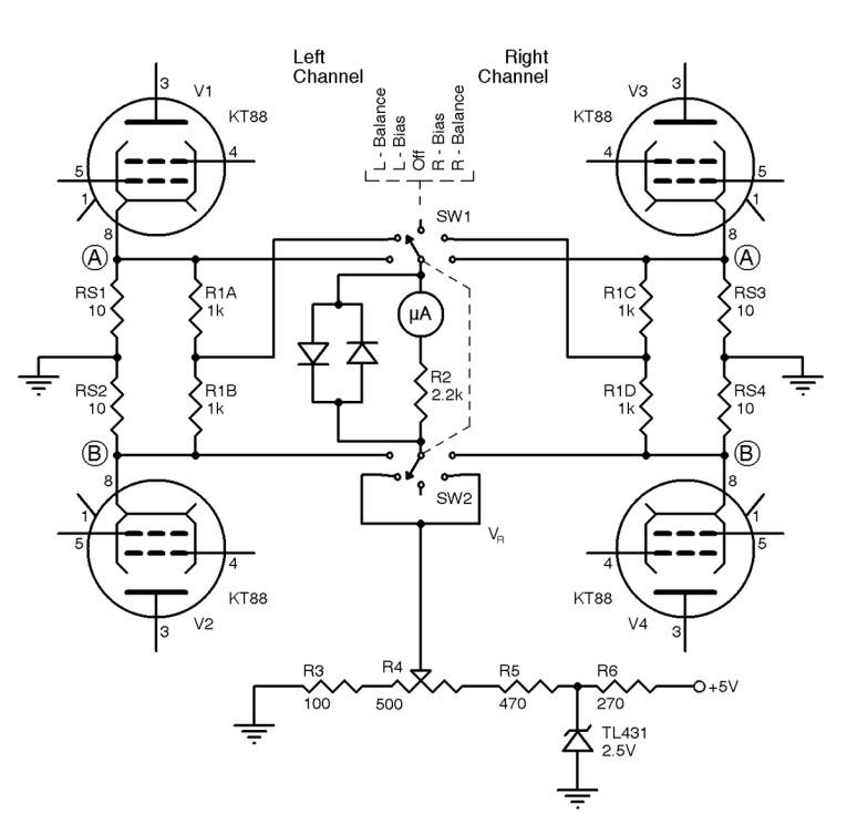
Push-pull output stages can be configured with bias and balance controls (see Figure 2a), or independent bias controls for each tube (see Figure 2b). I prefer the arrangement in Figure 2a, and this article describes the corresponding meter configuration. In the last section of this article, I describe how to modify the meter to work with independent bias controls. The meter is designed for fixed-bias amplifiers, not those with cathode bias. Cathode-bias amplifiers generally do not have bias adjustments, or if they do, the configuration varies widely, making it hard to recommend a specific bias-meter design.
The sense resistor in the cathode introduces a small amount of negative feedback, theoretically reducing both gain and distortion. In practice, the gain loss is minimal for the values recommended. For example, the predicted gain loss for a 10-Ω sense resistor and a triode-connected KT-88 with a 5-kΩ plate-to-plate load, mu of 8 and rp of 650 Ω is 0.2 dB. If this is a concern, you could shunt the sense resistors with a switch when the meter is not being used. Bypassing with a capacitor is not practical due to the low impedance of the sense resistor.
Several well-regarded classic amplifiers leave small sense resistors in the cathode circuit (e.g., Marantz 9, Heathkit W-7M, Luxman LX-33, Radford STA-25R, and Harmon-Kardon Citation II). I don’t feel there are any practical negative impacts of doing so. You can think of the sense resistors as being analogous to emitter degeneration resistors in a transistor differential pair.
In several of his designs, Hafler used a common resistor for the two push pull output tubes. This should prove somewhat better at reducing distortion, although it would not support the bias meter described here. It is interesting to note that he chose the specific value of 11.2 Ω in the patent pending Dynaco Mark III “Biaset” design, specifically because this value provided an optimal reduction in intermodulation distortion.[1] The Mark III User Manual describes a similar concept of calibrating the sense voltage by comparison to a reference voltage source, in this case, a fresh dry cell battery (1.56 V).[2]
Circuit Analysis
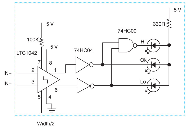
A Linear Technology LTC1042 window comparator IC is the heart of the meter. A window comparator provides a digital output when the input voltage is between the upper and lower limits of the window, hence the name. The LTC1042 has differential inputs, which can float between ground and the 5-V supply. As shown in Figure 3, the comparator drives three LEDs through logic gates, which indicate if the input is below, within, or above the window.
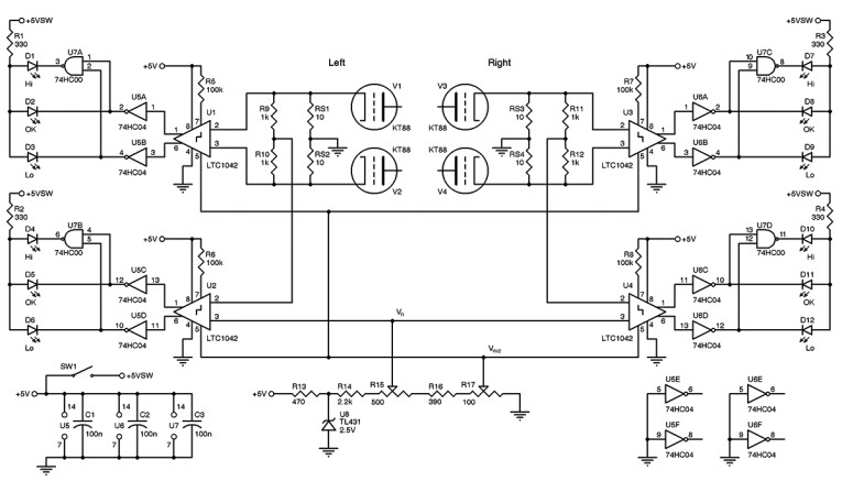
The sensitivity is controlled by the “width/2" input to the comparator. The “OK” LED illuminates when the difference in the inputs is less than ±width/2. The 100-kΩ resistor between pin 7 and the 5-V supply sets the internal oscillator frequency for the comparator. (It uses a sampled architecture to reduce power consumption.) Since only one of the LEDs is illuminated at a time, you can get away with a single-current limiting resistor rather than one per LED. Two of the basic window comparator circuits are used for each amplifier channel (see Figure 4). A TL431 precision voltage reference develops a stable 2.5-V source, which is divided down to provide the reference voltage (set by R4) and the width control voltage (set by R6).
The adjustment range is from roughly 40-to-80-mA target bias current per tube, with a window width of 0 to ±8 mA. The value of R1 is not critical but each pair should be matched. Their value should be less than 10 kΩ (per the input impendence guidelines in the LTC1042 datasheet) and large compared to the sense resistors.
The sense resistor value is a compromise between sensitivity and overload. I recommend sticking with 10 Ω in most cases. The comparator inputs will sit at 0.6 V for a typical 60-mA bias current, which is nicely within the 0-to-5-V range of the comparator. The maximum comparator input for no damage is 5.3 V, translating to 530 mA, which is well above what would be experienced in the normal operation or overload conditions. The LTC1042 accuracy is on the order of a couple millivolts, which translates to a few tenths of a milliamp error. Using a 10-Ω sense resistor makes it easy to remember how to set the reference voltage (reference voltage in mV = bias current in mA × 10).
Dissipation in the sense resistor (DC + worst case AC) is about 0.125 W. I recommend using a 0.5-W resistor to provide a safety margin. I didn’t bother with input protection since the 530-mA limit seems safe and the LTC1042 is inexpensive to replace if it is damaged. If you want to err on the side of caution, you could put a 1-kΩ resistor in series with each comparator input and clamp the input pin to the 5-V rail with a Schottky diode. This would also protect against the failure scenario in which one of the sense resistors blows.
Construction & Use of bias meter
The meter can be built into the amplifier, or you can use the same principle by bringing points A, B, and the ground to a connector and building the circuit externally.
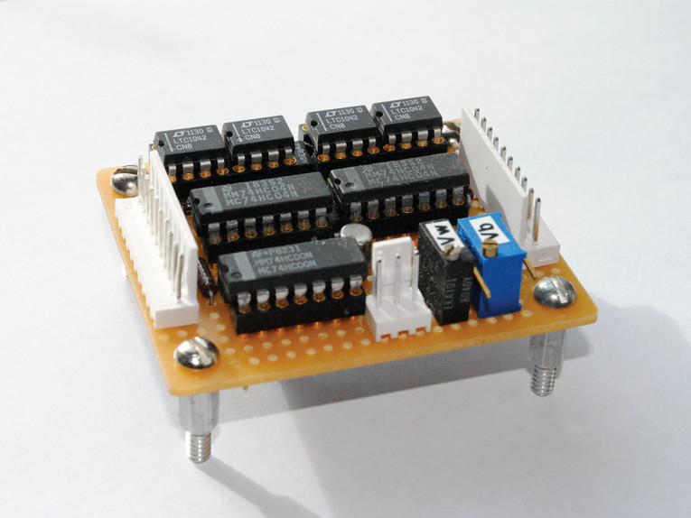
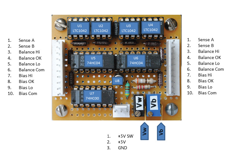
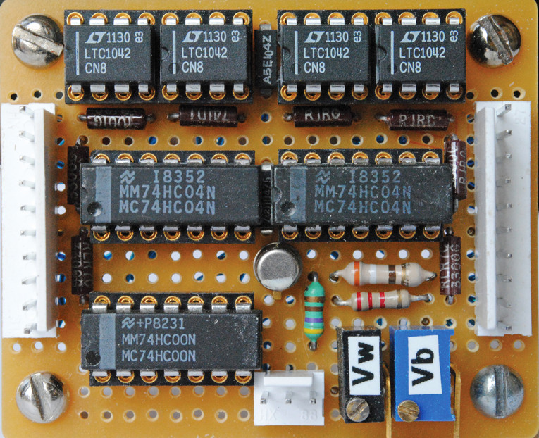
I built a stereo version of the meter shown in Figure 5 on a 2" × 2.5" perfboard with wirewrap construction. If you don’t have a lot of wirewrap experience, I would suggest using a larger perfboard and less dense construction. Total cost is roughly $30. You will need to provide a 5-V supply referenced to ground. To avoid damaging the ICs, you need to apply power to them anytime the amplifier is powered. During normal operation of the amplifier, the LEDs will switch on and off with the audio signal. SW1 enables them to be disabled to avoid coupling noise into the audio circuits. Install the LEDs beside their corresponding adjustment potentiometer.
Adjust R15 to correspond to the desired idle current using a DVM. For example, a 60-mA idle current target corresponds to 600 mV. Adjust R17 for the desired sensitivity. For example, a ±4-mA window corresponds to 40 mV at the wiper of R17. Once the reference voltage is set, it will be stable. There is no need to check or adjust it in normal operation. In operation, adjust the bias and balance potentiometers until the middle LED is illuminated with the amplifier idling (warmed up, with no input).
Additional uses
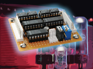
The LTC1042A design (see Photo 2) can form the basis of several other useful circuits in a tube amplifier. For example, if you have a design with a DC balance control in a phase splitter, you
can divide down the plate voltages with 100:1 voltage divider (1-MΩ and 10-kΩ resistor) and then use the same basic window comparator block. It can also form the basis of an overload detector, sensing an over-current situation in the output tubes and shutting down the power supply at an accurate trip point.
Parallel output tubes & bias controls
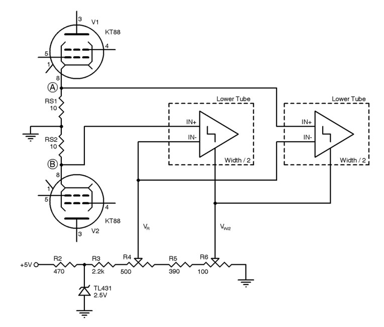
Many amplifiers have independent bias controls such as shown in Figure 2b. In the case of parallel output tubes, this is almost always true. The meter can be modified to work with independent bias controls (see Figure 7). Each sense resistor input is compared to the common reference voltage and measures bias on the corresponding tube. There is no balance measurement, per se. The bias is set to be identical on each tube, inherently achieving balance. For parallel output tubes, simply replicate the comparator circuit for each tube, using a single reference voltage circuit (Figure 8). aX
References
[1] D. Hafler, “New Amplifier with KT-88s,” Radio-Electronics Magazine, 1958.
[2] Dynaco, “Instructions for Assembling the Dynakit Mark III,” www.curcioaudio.com/mk3_mnl.pdf
Resources
J. Stewart, “Safe Bias and Balance Measurement,” Glass Audio Projects— 17 Vacuum Tube Designs, Audio Amateur Press, 1997.
Turner Audio, www.turneraudio.com.au/Integrated5050.htm.
 Parts and Components
Capacitors
• C1–C3 = 100n decoupling capacitor
Miscellaneous
• SW1 = SPST switch
• U1–U4 = LTC1042 window comparator
• U5, U6 = 74HC04 hex inverter
• U7 = 74HC00 quad NAND gate
• U8 = TL431 precision voltage reference
Resistors
• R1–R4 = 330R, 1/8 W
• R5–R8 = 100 kΩ, 1/8 W
• R9–R12 = 1 kΩ, 1/8 W (matched pairs)
• R13 = 470R, 1/8 W
• R14 = 2 kΩ2, 1/8 W
• R15 = 500 R 10-turn trimpot
• R16 = 390 R, 1/8 W
• R17 = 100 R 10-turn trimpot
• RS1–RS4 = 10 R, 0.5 W
Semiconductors
• D1–D12 = LED (Above/Below—Red; OK—Green)
This article was originally published in audioXpress, July 2012.