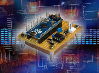
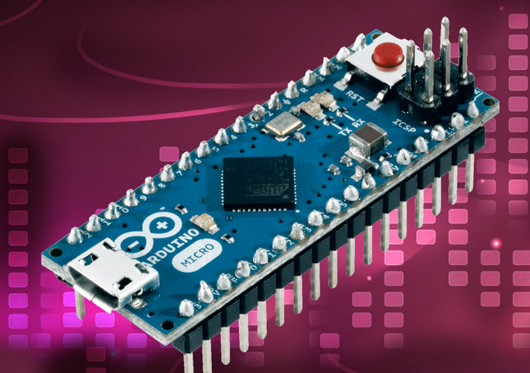
The Arduino is a popular open-source microcontroller. For less than $25, you can have a compact and sophisticated controller, plus a huge network of open-source software and support. In the power amplifier controller project, the Arduino detects the presence of an audio signal and automatically powers on the amplifier, stepping through a timed sequencing of filament and B+ power supplies. It turns off the amplifier several minutes after the audio signal is lost, helping to increase the life of the tubes while preventing unnecessary power cycling. The controller also has an override switch to manually turn the amplifier off or on, independent of the audio signal.
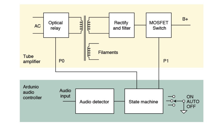
Figure 1 shows how the Arduino audio controller connects to the tube amplifier. The audio detector consists of a hardware precision rectifier combined with software processing. It detects the audio input signal’s presence. The state machine is the software that controls the logic and the timing of the two control signals, P0 and P1, based on the audio detector and the mode switch. The P0 signal switches AC to the amplifier’s power transformer using an optoisolated, zero switching relay. The P1 signal drives an optoisolated MOSFET switch and controls the B+ power.
My article, “Arduino-Based Tube Power Amplifier Controller” (audioXpress, February 2015), has additional details on how the software works and the design of the MOSFET switches based on the IXYS FDA217 isolated MOSFET driver (see Resources).
Bias Meter Recap
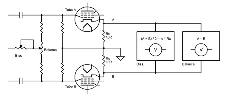
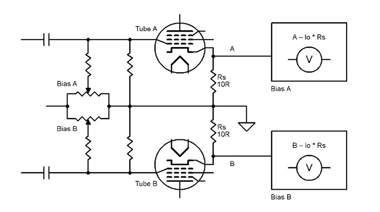
The bias meter works by inserting 10-Ω sense resistors, RS, in the cathode legs of the push-pull output tubes. The voltage across the sense resistors is measured and used to control LEDs, which indicate if the bias is properly set. There are two common variations of tube bias controls. I will refer to Figure 2 as the bias/balance arrangement and Figure 3 as the independent bias arrangement. The bias meter can work in either configuration. In the first, the average and difference voltages drive the calibration LEDs. In the second, each LED is driven based on an individual tube’s sense voltage.
My original design, which I detailed in a 2012 audioXpress article uses a hardware window comparator (LTC1042) to control three LEDs (red, green, and yellow) per bias adjustment. In operation, the bias controls are adjusted until the corresponding green LED lights. The desired tube bias, Io, is set with a single trim pot and needs only be adjusted once when the meter is built.
Combined Design
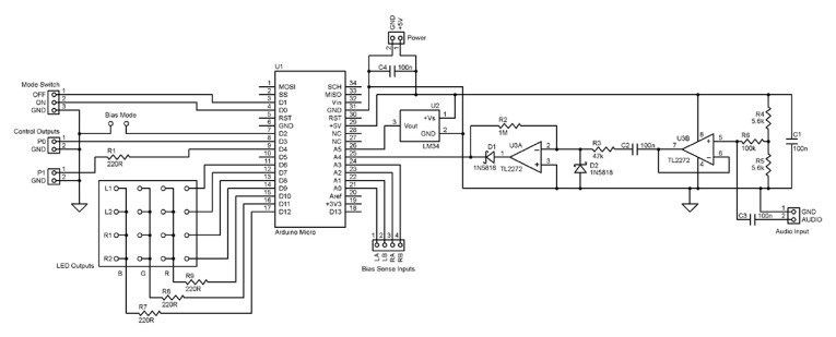
In the bias meter’s new implementation, I simply connected the bias sense resistor voltages to four of the unused analog to digital converter (ADC) inputs on the Arduino and drove the indicator LEDs using a software version of the window comparator function. Figure 4 shows the combined design.
An extra Arduino input pin (D5) is used to select the bias mode. If this input is grounded, then each window comparator directly uses the sense voltage (independent bias mode). If the input remains unconnected, then the average and the difference are taken before the window comparator (bias/balance mode).
To save on output pins, the LEDs are driven in a multiplexed configuration. They are arranged in a matrix (four LEDs × three colors), and the software quickly cycles through them, lighting one LED in the matrix at a time by controlling the associated row (LED) and column (color). This happens faster than the eye can detect, so the LEDs appear to be continuously on.
Rather than use three physically separate LEDs for each bias point as in the earlier design, I selected an Red/Green/Blue (RGB) LED. These have three LED devices in one package, in this case with a common anode. That way you only need a single mounting hole adjacent to each bias control to mount the LED. Thanks to a bit of extra software, the bias error is more accurately indicated with a combination of solid and flashing LED colors (see Figure 5).
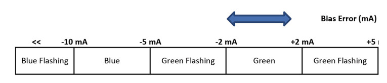
To turn on calibration mode, a double pole single throw (DPST) switch is used to take the Manual ON and Manual OFF inputs both low. The software interprets this as calibration mode. If the calibration mode is selected while the amplifier is off, then it is turned on and goes through the normal power cycling. The desired bias point is set in the software and easily modified by the builder, as is the nominal 2-mA sensitivity. If you adjust the 2-mA threshold, then the 5- and 10-mA thresholds will proportionally scale. With 10-Ω sense resistors, the full-scale current that the meter can measure is 250 mA per tube.
To use the bias meter, remove the audio input to the amplifier and turn on the calibration switch. Adjust each bias control until the corresponding LED is solid green. It is good practice to let the amplifier stabilize for 30 min or so prior to adjusting bias. I added an LM34 temperature sensor and software functionality to shut down the amplifier in an overtemperature condition. The LM34 provides an accurate output of 10 mV/F in an inexpensive TO-92 package. If the temperature exceeds 120°F then the amplifier shuts down and the bias LEDs are alternately flashed red at 2 Hz. When the temperature drops below 120°F the amplifier will restart in whatever mode it was in previously (manual on, automatic, or calibration).
You can adjust the threshold in software. I made a couple of simplifications to the controller portion compared to the earlier design. Only one analog input is used—since we just need to sense the presence of audio, either left or right channel will suffice. Also, I removed the ability to independently control the output and driver B+ voltages (which eliminates the P2 control from the original design).
Building It
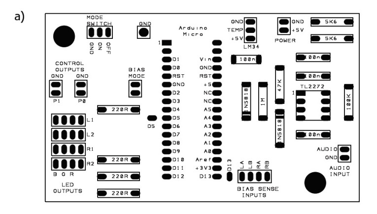
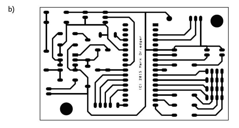
The PCB design, shown in Figure 6a (component side) and Figure 6b (solder side), is 3.75” × 2.25”, single sided and uses through-hole components to make construction easier. A soft copy of the layout for PCB Artist software is available in the Supplementary Materials section of audioXpress’s website. If you are using the bias-only configuration, then short the “BIAS MODE” pins together with a jumper. For bias/balance mode, leave the “BIAS MODE” pins unconnected. If you are not using the LM34 temperature sensor, then short the TEMP and GND pins where the LM34 would normally be installed. For this design, I have assumed the LEDs would be mounted adjacent to each bias pot and wired to the PCB. If instead you want to directly install the tricolor LEDs on the PCB, you will need to insulate the common anode (long lead) and bend the leads to swap the red and common anode leads. You may also need to swap the blue and the green leads as there are two pinout variations on the market.
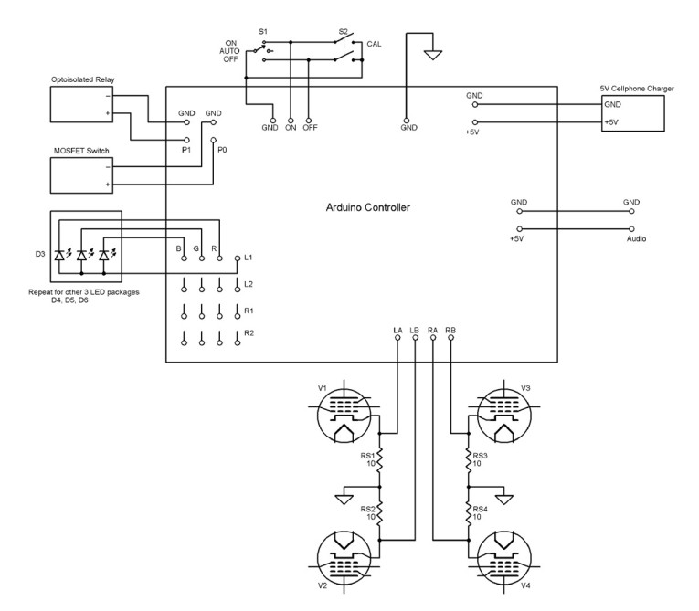
Figure 7 shows how the controller is wired to the amplifier. It is continuously powered by a small 5-VDC cellphone charger. Make sure that there is a ground connection between the controller and amplifier. More details on the MOSFET switch design can be found in my February article.
Always observe proper safety precautions when working on the AC voltages and tube amplifier high-voltage supplies. Unplug and safely discharge all the capacitors before working on the amplifier. If you are not comfortable doing something, then don’t attempt it.
Installing Software and Configuring
My February article also contains full instructions on installing and running the Arduino software. Here is a summary:
• Download and install the Arduino Integrated Development Environment (IDE) software from www.arduino.cc.
• Retrieve the software “sketch” from the audioXpress supplementary materials by downloading and unzipping the file “AC_V2_00.zip”. This will create a directory called “AC_V2_00” with two files. Move this directory to the default Arduino sketch folder (look under File, Preferences in the IDE application if you are not sure where this is).
• Open the sof tware sketch from the IDE application (File, Open, “AC_V2_00”).
• Change any of the parameters you want to modify. They are defined at the top of the file.
-- Filament warm up delay (ON_DELAY, default 10 s)
-- Amplifier shut down delay (OFF_DELAY, default 45 s)
-- Target amplifier bias current (TARGET_BIAS, default 62.5 mA)
-- Window comparator sensitivity (THRESHOLD_BIAS, default 2.0 mA)
-- Over-temperature shutdown threshold (THRESHOLD_TEMP, default 120.0 F)
-- Output tube cathode resistor (RS, default 10 Ω)
• Connect the Arduino module to your computer using the USB cable and upload the software (File, Upload). You may need to select the Arduino type (micro) and COM port (varies with your computer) from the Tools menu in the IDE.
• Disconnect the USB cable and install the Arduino module in the controller circuit. If you need to reprogram it, remove the Arduino module from the power amplifier for safety.
Final Thoughts
The Arduino’s software flexibility makes it easy to implement a wide range of functions with a simple hardware design. And, the Arduino can do much more. The open-source Maker Movement is overflowing with interesting possibilities. You can find online projects for preamplifier switching and control, MP3 players, DACs (e.g., hifiduino.blogspot.com), and many types of test equipment. With a bit of time, I am sure you can add your own innovative applications to the mix.
This article was originally published in audioXpress, May 2015.
| Capacitors | |
| C1–C4 | 100 n |
| Components | |
| U1 | Arduino micro module |
| U2 | LM34 temperature sensor |
| U3 | TL2272 or similar single-supply dual op-amp |
| Diodes | |
| D1, D2 | 1N5818 |
| D3–D6 | RGB LED, common anode |
| Fuses | |
| S1 | SPDT, center off toggle switch |
| S2 | DPDT toggle switch |
| Miscellaneous | |
| Cellphone charger 5 V | |
| Optoisolated relay | |
| MOSFET Switch | |
| Resistors | |
| R1 | 220 Ω, 0.25 W |
| R2 | 47 kΩ, 0.25 W |
| R3 | 47 kΩ, 0.25 W |
| R4, R5 | 5.6 kΩ, 0.25 W |
| R6 | 100 kΩ, 0.25 W |
| R7–R9 | 220 Ω, 0.25 W |
| RS1–RS4 | 10 Ω, 0.5 W |
Project Files
To download additional material and files, visit audioxpress.com/page/audioXpress-Supplementary-Material.html.
Resources
M. Driedger, “Arduino-Based Tube Power Amplifier Controller,” audioXpress, February 2015.
——— , “An Accurate Bias Meter for Push-Pull Tube Output Stages”, audioXpress, July 2012.
Sources
70S2-04-B Opto-isolated relay Magnecraft (now Schneider Electric) | www.schneider-electric.com
TLC2272CP Op-amp Texas Instruments, Inc. | www.ti.com