The audibility threshold depends on many factors; reports vary from about 100μS to 2mS. A sufficient amount, though, is certainly audible, as visualized by the “reductio ad absurdum” example of the midrange being delayed by one minute relative to the treble!
Crossovers
A true first-order (neither driver polarity inverted) CO produces a square-wave (step) response limited in perfection only by the drivers. For second- and higher-order COs, there is one type that can also (ideally) have a perfect step response, as described by John Kreskovsky in “A Transient-Perfect 2nd Order Passive Crossover” (aX May '013). This type uses extensive frequency overlap and/or amplitude peaking. But most standard high-order COs (e.g., Butterworth and Linkwitz-Riley) produce an all-pass type phase nonlinearity of order one less than the CO order. For example, a third order CO has a second-order all-pass response.
In this article, I show the step responses of various numbers of cascaded first-order (non-resonant) all-pass stages. These have a flat amplitude response (DC-50kHz) but a nonlinear phase versus frequency curve, which produces a varying delay versus frequency relation.
The All-Pass Circuit
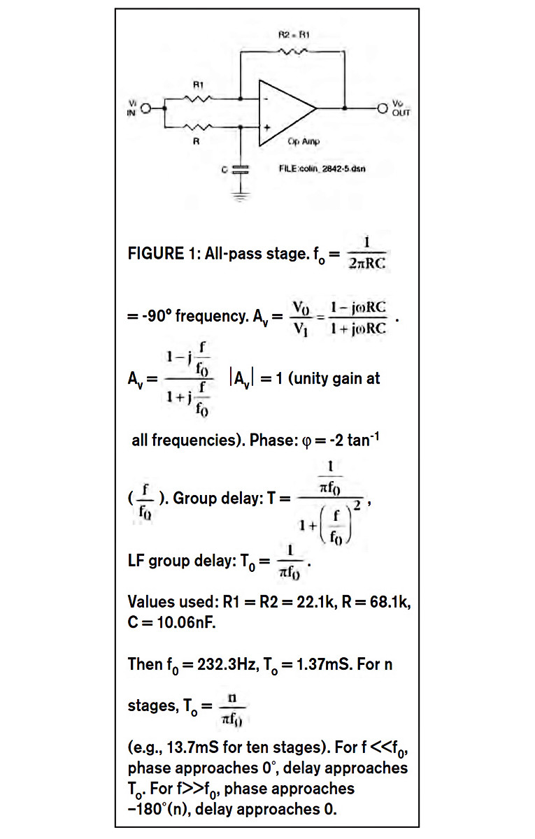
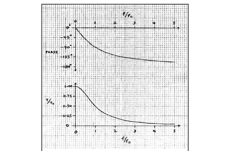
Figure 1 shows the op amp circuit, ten of which I cascaded on a breadboard with a jumper wire selecting 1 through 10 stages (first- through tenth-order all-pass response). Figure 2 shows the phase shift and group delay of a single stage on linear frequency scales. Group delay is the negative of the phase versus frequency slope, and generally (but not always) corresponds to the propagation delay of a group (band) of frequencies in a transmitted signal.
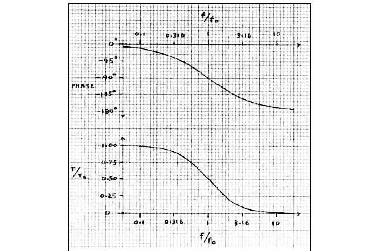
Figure 3 shows the same data with log frequency scales. Note that the curves are now symmetrical about fo, where the phase is –90° and the group delay (T) is down to half the LF value (To) of 1/πfo, which T approaches for f<<fo. Thus, low frequencies are delayed relative to high frequencies (which approach zero delay). Correcting this in real time is physically impossible over an unlimited bandwidth (required for perfect step response), without an infinite number of correction stages or a negative-delay (“crystal ball”) circuit! However, it is possible over a limited bandwidth by progressively delaying the higher frequencies to match the LF delay.
This can be done digitally, but Dick Crawford (“The Phase Redeemer,” SB 5/97)4 has done this with an optimized combination of all-pass phase-shift networks. He used five cascaded second-order stages to reduce the delay dispersion of a second-order CO from 57μS to 18μS, a reduction of 39μS. The compensation circuit itself delays the highest audio frequencies 50μS more than the lowest frequencies. Photos 1 and 2 of Mr. Crawford’s article (p. 36) show the CO’s first-order all-pass step response greatly improved by the compensator.
The HF wiggles are of no consequence, because they range from about 27-40kHz. Mr. Crawford used resonant second order all-pass networks. Besides having double the phase excursion (0° to 360°) of a single stage, using resonance (Q greater than 0.5) sharpens the phase versus frequency curve. This allows higher frequencies to be delayed more than lower frequencies over a limited bandwidth, which is exactly what most speaker COs need.
In this article, I’ve used only first order all-pass networks, which are non resonant both singly and in cascade. The following waveform descriptions serve to illustrate the step responses of idealized (flat summed amplitude versus frequency) higher-order speaker COs.
All-Pass Time Response Images
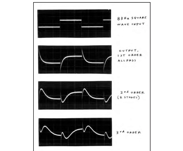
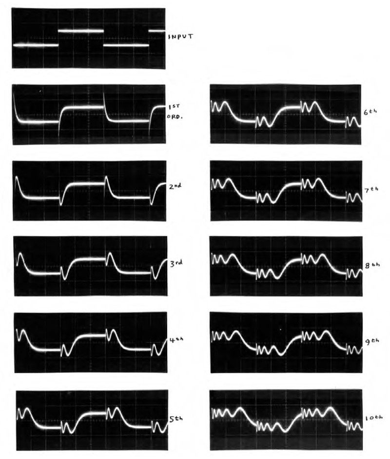
Figure 4 shows the input 83Hz square wave and the outputs of 1, 2, and 3 stages of cascaded all-pass networks (that shown in Fig. 1). For up to three stages, I used the 83Hz square wave and a 2mS/div. time scale, so the responses’ initial spike (of opposite polarity to the input step for odd number response order) would be (at least barely) visible.
In Fig. 5 I slowed the driving frequency to 33.3Hz and lengthened the time scale to 5mS/div. This is so that even with ten stages (lower right waveform), the response would have time to settle before the next step transition arrives. The tenth-order all-pass (ten cascaded Fig. 1 circuits) clearly shows the instantaneous HF transient response, followed by progressively delayed lower frequencies. It’s important to remember that the amplitude/frequency responses are all very flat (hence the name “all pass”). Using TL074 quad op amps, this response even through ten stages is ±0.09dB from DC –50kHz.
If you turn Fig. 5 upside down, the time-reversed waveforms are what you would need to perfectly compensate this delay dispersion. Even the first-order response shows the physical impossibility of real-time, zero delay, unlimited bandwidth correction: The hypothetical “compensator” would need to “know” when the input step was going to arrive, and anticipate it by starting a positive (growing) exponential curve (mathematically starting from the infinite past!), and then magically stopping “on a dime” at the precise input step moment. Twilight Zone music, please!
Once, in the 1970s, I did compensate an all pass, but not in real time: I passed a square wave through a first-order all-pass, recorded it on tape, then played the tape backwards, feeding the time-reversed signal through the same all-pass. Within the limits of tape reproduction, lo and behold, out came a reasonable square wave!
The initial response transient, barely visible in the first- and second-order responses in Fig. 5 (viewed right side up), become invisible in the higher order waveforms. But they are there, of opposite polarity to the input step for odd-numbered orders, and of the same polarity for even-numbered ones.
This is because each stage has a –180° shift (same angle as +180°) for frequency components well above the fo of 232Hz. One rule to remember: After reaching steady-state response, the number of voltage-direction excursions in response to an input step is one more than the number of stages of all-pass.
For example, in the first-order response (one stage), the output initially jumps in the opposite direction to the input, then reverses direction, exponentially decaying to the input voltage level. The higher-order step responses resemble a non-uniformly stretched spring. Listening to electronic pulses (e.g., a 1Hz square wave) through ten stages of all-pass shows a dramatic effect: The sharp input click becomes a downward swooping “teeooup” sound. The instant attack sound of the input is almost completely smeared.
Group Delay
As Bill Waslo pointed out in his article, group delay doesn’t necessarily correspond to actual time delay; nor does a constant group delay ensure distortionless waveform transmission. Constant group delay means a linear phase versus frequency relation. But for waveform reproduction fidelity, this straight phase/frequency line must pass through 0°, or an integral multiple of 180°, at zero frequency (DC).
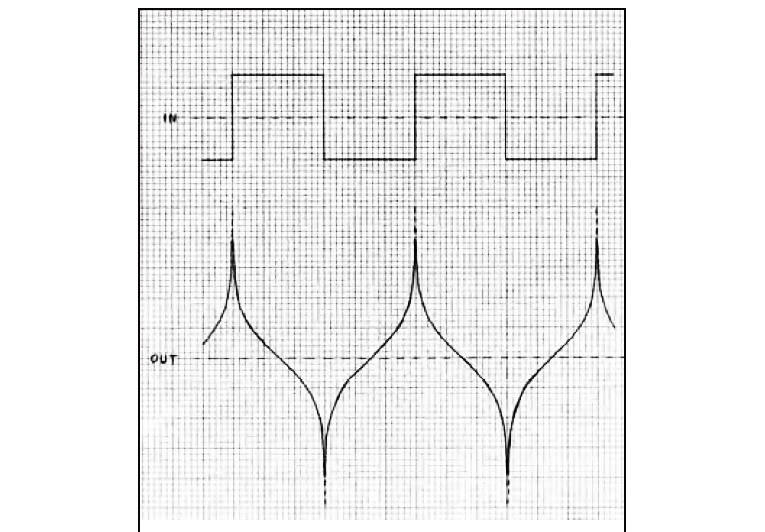
Figure 6 is an example of a constant 90° phase shift (Hilbert transform) acting on an ideal (zero rise time) square wave. The phase/frequency relation is linear, so group delay is zero. But because of the constant 90° offset, the square wave is obviously not preserved! This ideal 90° constant-phase processing is not physically possible in real time: First, note that the curved response must “crystal ball” anticipate the square wave steps. Second, at the input transitions, the output reaches plus and minus infinity! Yet the output’s harmonic amplitudes are identical to those of the square wave. The RMS value is also unchanged.
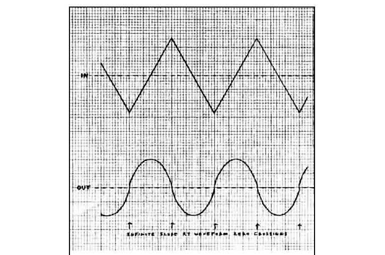
Using the backwards tape recording method previously described with a phase-shift network, I was able to generate a reasonable approximation of this waveform. It did sound almost the same as the square wave. Figure 7 shows the effect on a triangle wave. The point is that constant group delay doesn’t guarantee waveform fidelity. However, for the simple all-pass networks used in this article (and for well-aligned speaker COs), the calculated group delay corresponds reasonably well with actual signal delay. Because a crossover of order “n” has the phase characteristic of (n – 1) cascaded all-pass stages, the maximum frequency dispersion of an nth-order CO, with CO frequency of fo, is Tmax = (n – 1)/πfo.
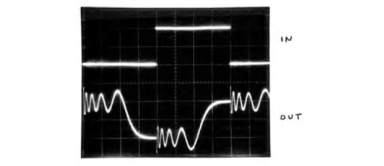
For example, a fourth-order CO at 200Hz has a Tmax = 4.77mS, and a third-order CO at 2.5kHz has a Tmax = 255μS. Figure 8 shows the ten-stage all-pass response to a 25Hz square wave. The initial response transients, of the same polarity as the input steps, are too quick to be visible with the 5mS/div. time scale. Note that the output waveform crosses zero about 12.6mS after the input step. This is close to the network’s LF group delay of 13.7mS.
In Fig. 9 a 25Hz triangle wave was used to drive the ten-stage all-pass. The time scale is 10mS/div. The triangle wave’s (odd) harmonics roll off at –12dB/octave, twice the rate of the square wave harmonics. That’s why the HF transient response wiggles are much lower in amplitude than with the square wave.
The triangle’s harmonics up to the ninth are lower than the 232Hz all-pass center frequency. But even the fifth harmonic is 28dB below the fundamental amplitude. At its frequency of 125Hz, the all-pass group delay has only dropped to 77.5% of the initial (very low frequency) value.
Because of this, the triangle’s shape is reasonably reproduced, delayed by close to the network’s 13.7mS LF group delay value. This demonstrates how a large number of cascaded all-pass stages can produce a reasonably faithful waveform delay over a useful bandwidth proportional to the number of stages.
Steep Crossovers
Some newer speaker designs use very high-order COs, such as sixth and higher. One manufacturer advertised so-called “infinite slope” COs. If taken literally, there would be infinite LF delay; that is, the bass would never come out! I think that speaker used transmission zeroes (notch filters) to generate very steep slopes over a very narrow band. In any case, the speaker’s transient response should be interesting!
Compensation Of Delay Dispersion
Note: Although I’ve used non-resonant all-pass responses to represent speaker CO summed response dispersion, the all-pass characteristic of many COs has resonant Q values (greater than 0.5). This is typical of third- and higher order Butterworth COs, for example. A resonant all-pass Q doesn’t (in a well aligned CO) produce amplitude/frequency errors; it steepens the phase versus frequency slope around the CO frequency.
This, for high enough Q values, can increase the group delay around the CO frequency to a greater value than the LF delay. But regardless of Q value, all second- and higher-order COs (except the special class of transient-perfect COs referred to earlier) produce a delay that drops toward zero at frequencies much above the CO frequency. Therefore, a delay compensator must delay higher frequencies more than lower frequencies, over the full audio band, or at least over the frequency range where delay dispersion is considered to be possibly audible. (For me, this range is about 30Hz to 5kHz.)
This can be accomplished by the use of cascaded resonant all-pass networks, with an optimized distribution of fo and Q values, as Dick Crawford has done. Designing such a compensator requires consulting a filter design book that includes delay equalizers, or else a long time spent doing trial and error experimentation with a good simulation program. (If you do this with actual circuit breadboarding, be prepared to spend a really long time!)
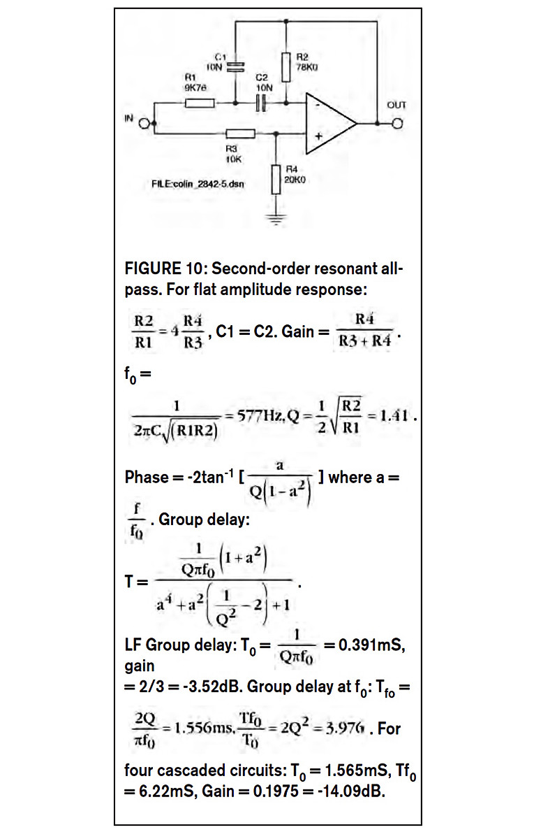
A Resonant Second-Order All-Pass Circuit
Figure 10 shows a circuit I built, based on Dick Crawford’s article (4). I cascaded four of these to get an eighth-order resonant all-pass. Resonance (Q greater than 0.5) steepens the phase versus frequency slope, but does not produce an amplitude peak. (It’s still an all-pass, meaning flat amplitude versus frequency response.)
Because it’s second-order, the circuit of Fig. 10 has a phase shift that varies from 0° to –360° as frequency varies from zero (DC) to infinity. Of course, -360°, like +360°, is the same (non) angle as 0°. But –360° here means that as frequency is increased from zero, a sine wave is progressively delayed (phase shifted) until, at frequencies much higher than fo (where the phase is –180°), the wave is delayed by an amount approaching a full cycle.
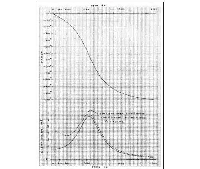
Figure 11 shows the phase and group delay (solid curves) of the cascade of four second-order stages. At the fo of 577Hz, the phase shift is –720°; that is, a 577Hz sine wave is phase-shifted by two full cycles. The group delay starts at 1.556mS (the To value) and increases to a peak around 530Hz of about 6.4mS.
Then the group delay drops steeply, for example, to 0.332mS at 1.5kHz. The dashed curve is the group delay of this same eight-stage resonant all-pass additionally cascaded with two stages of the first-order (non-resonant) all-pass circuit previously described. Note how the delay variation from DC to 500Hz is reduced. The eighth-order resonant all-pass is by no means an optimized compensator for the decreasing delay versus frequency of the two first-order cascaded all-pass stages (the group delay of one of which is shown in Figs. 2 and 3). Between about 220 and 520Hz, the resonant eighth-order all-pass is overcompensating the non-resonant all-pass’ downsloping delay.
However, I didn’t attempt to design a delay compensator; rather, I simply wanted to be able to view step responses of — and listen to the effects of — a high-order resonant all-pass. But once having done this, I was curious about cascading it with the existing 1-10 stage selectable first-order all-pass breadboard. Despite the overcompensated group delay (dashed curve in Fig. 11), using only two first-order stages produced the most symmetrical square-wave response.
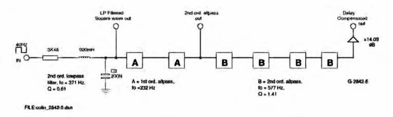
Delay Compensation Experiment
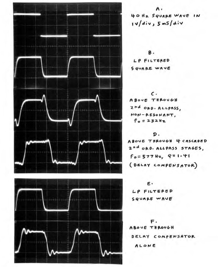
Figure 12 shows the setup. For the test signal, I filtered the input 40Hz square wave with a second-order low-pass filter, with a Q of 0.61 giving a maximally flat step response (Bessel or linear phase approximation). The filter’s fo of 371Hz is sufficiently below the cascaded all-pass’ peak delay frequency of 530Hz, so as to minimize step response wiggles from higher frequencies where the group delay drops.
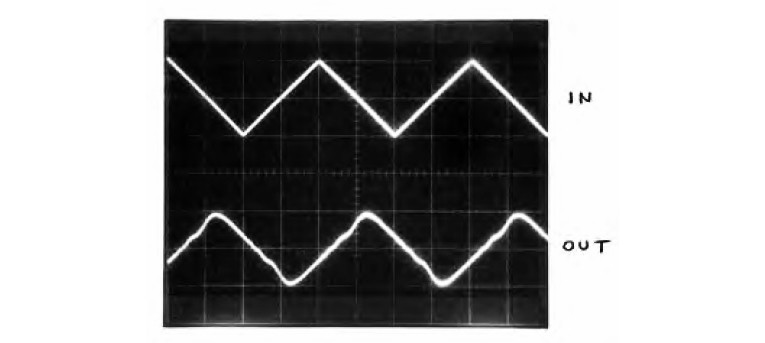
Figure 13 shows the results. The filtered square wave in waveform B is the test signal. Waveform C shows the response of the second-order all-pass circuit, similar to a third-order speaker CO. This is then fed through the eighth order resonant all-pass, whose output is waveform D. Note how, compared to C, the shape is more “square” overall, with steeper sides and reduced overshoot. The small HF wiggles in D are from the crude, far from optimized delay compensation I mentioned. But you can see the basic principle at work here. Note the delay of about 4mS.
Interestingly, selecting only two stages of first-order all-pass produced the best square-wave response, even though using three or four stages produces less overall delay variation from DC to 500Hz. This could be because, as previously mentioned, group delay doesn’t always correspond to actual signal delay. For example, a first-order high-frequency boosting shelf response (such as that produced by speaker diffraction spreading loss) actually has a negative group delay around the center of the upward slope region. If this corresponded to actual signal delay (negative), your speaker would produce music before the input signal arrived! Just think: Enough of this could allow you to hear tomorrow’s winning lottery number today!
OK, back to the real world. Note that waveform D is more symmetrical than B. The extra HF delay compensation of the eighth-order resonant all-pass appears to be compensating the LF (re HF) delay dispersion of the low-pass filter used in the test signal. Waveform F in Fig. 13 is the response to the filtered square wave (E) of the eighth-order resonant all-pass by itself (without the second-order non-resonant all-pass). Note that the lower frequency filtered step excursion responds before the most prominent higher frequency wiggles. This is from the rising delay curve in Fig. 11, the lower solid curve from DC to 530Hz.
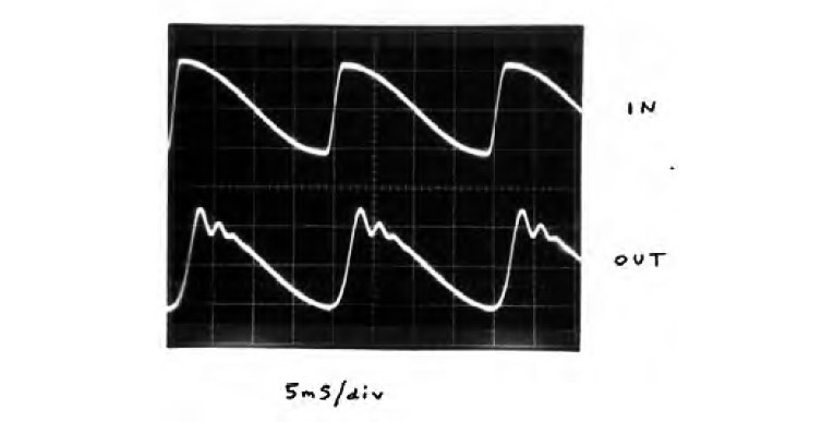
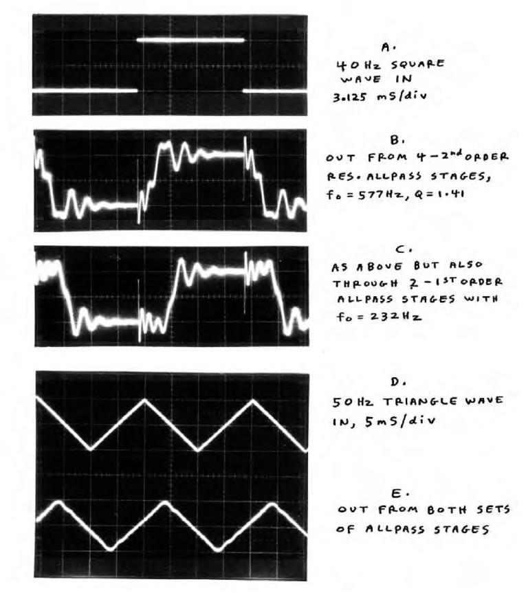
Figure 14 shows this same effect with a 50Hz duty cycle offset sine wave from an old HP8116A function generator.
Response to Unfiltered Square Wave
In Fig. 15, waveform A is a 40Hz square wave, and B is the response from the eighth-order resonant all-pass. C is the response through the combination of the eighth-order resonant and second-order non-resonant networks. B and C display the group delay variations shown in Fig. 11, bottom, the solid and dashed curves, respectively. In waveforms B and C, the first arrival is the faint short spike, containing the highest step pulse frequencies that are delayed very little.
In C, you can see this spike “springing” into ripples of decreasing frequency. This represents the increasing delay as the frequency in Fig. 11 decreases from above 1.5kHz to 530Hz. Then (back to Fig. 15C), the signal makes its large step excursion toward the opposite square wave polarity. Notice that the delay from the initial spike to the step excursion midpoint (at zero volts) is about 4mS. In Fig. 11, dashed curve, the LF group delay (from DC to about 300Hz) is close to this 4mS value.
From about 5 to 7mS after the initial spike, you see another set of prominent wiggles (after each step transition). This corresponds to the 380 – 660Hz region in Fig. 11 (dashed curve), where the group delay ranges from 5mS to the 6.8mS peak value.
Listening to low-frequency step pulses(1Hz square wave) through the eighth order resonant all-pass, I could easily hear the effect. Unlike the cascaded first order non-resonant all-pass’ downward sweeping “teeooup” sound, the resonant all-pass turned the sharp 1Hz squarewave’s clicks into a sort of “chuwik” sound.
Of course, lasting only 6.4mS, the sound was much quicker than trying to say “chuwik,” but this invented word describes the effect of the group delay dispersion, where I could hear the sound start with the highest frequencies, which quickly swept downward, and then partway back up. It sounded like some kind of quick bird chirp. If you think this analysis is “for the birds,” remember that they’re probably the original inventors of music!
Triangle Wave Response
Because the triangle wave has much lower harmonic amplitudes than the square wave, the 50Hz triangle response in Fig. 15E has much lower HF ripple amplitude. The cascade of both all-pass networks then displays a reasonably clean waveform delay of about 4mS, which agrees with the LF group delay value.
Audibility Issues
1. Delay dispersion itself, heard on a single driver (e.g., headphones) is probably not audible below 1-2mS. One exception, though, is with loud steady-state tones having a coherent but low-order harmonic spectrum, such as flute and organ tones. Especially with asymmetric waveforms having even harmonics, you can hear phase shifts and even simple polarity inversion. This is because of the ear’s asymmetric nonlinearity — about 1% at 90dB SPL below 1kHz, and much greater for louder and lower frequencies. Phase shifts including inversion can change the ear’s own added harmonics and IM tones. Furthermore, the auditory nerve cells fire predominantly on negative waveform half-cycles, at least for the lower frequencies.
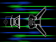
2. Spatial driver separation enhances the audibility of delay dispersion, because in a fast, wideband transient the higher frequencies come out of, say, the tweeter first; then the delayed delayed lower frequencies come out of a different position, say, the woofer. A fast, swooping motion can be sensed. And even if the two drivers are close compared to the listener’s distance, inter-driver phase shifts enhance the sense of separation. This is similar to left-right stereo phase differences near 180° producing a sound stage perception extending beyond the speaker positions (used in some boom boxes and TVs with built-in closely spaced speakers for “enhanced stereo”).
3. Delay dispersion can increase or decrease a waveform’s peak amplitudes (while not affecting the RMS levels). Note how even the first-order all-pass in Fig. 4 triples the square waves’s peaks from ±0.5V to ±1.5V. Some musical waveforms can have their peaks reduced, depending on the time and spectral structure.
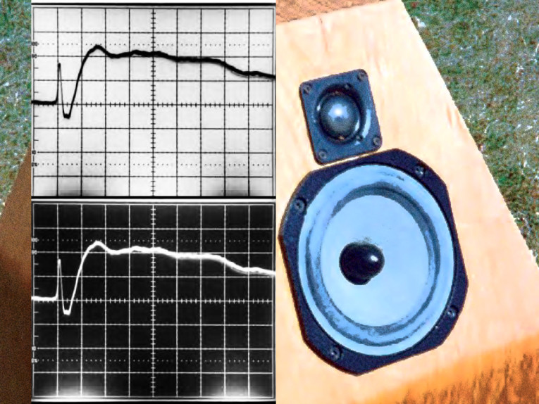
As mentioned, the ear’s nonlinearity, especially for loud sounds below 1kHz, is sensitive to waveform peaks. Therefore, delay dispersion can affect the impact and realism of drum strikes, string attacks, and other powerful transients, even if the delay dispersion itself is inaudible. These effects can be quickly revealed with the pulses from the Sound Strobe, reviewed by Ed Simon in aX April ’07. Because lower frequency COs have higher time delay dispersion (it’s inversely proportional to frequency), a fourth-order woofer/mid CO, having (at best) the step response shown in Fig. 4 (lower photo), could easily produce audible degradation. With a CO frequency of 200Hz, the woofer output is delayed 4.8mS relative to the midrange, not counting extra woofer time lag. This is equivalent to a 5.4´ path length difference.
Now consider the effect on a musical transient of this and a woofer/midrange spacing of 2´: A live bass string plucking transient emanates from a few inches of string and soundboard. (The rest of the string’s length and the soundboard area produce delayed resonances, but the sharp initial transient radiates from a small area.) But from the speaker, the transient is frequency smeared over a 2´ high by 5´ deep area! I have no problem hearing this effect even with a second-order woofer/mid CO, in comparison with a waveform phase-preserving first order CO.
For example, my two best speaker systems are the Swans M1 with Scan-Speak sub (aX Sept. ’05 - 5) using a second-order CO, and the Venue Speaker (aX Nov. ’06 - 6) with first-order woofer CO. Both have a very flat in-room response down to about 30Hz. But the attack transients of electric or acoustic bass, low piano notes, drums, and low-pitched guitar notes sound naturally precise (clean “bite” or “snap”) on the first-order Venue. On the second-order Swans/Scan-Speak, these attack transients still sound clean, but not quite as naturally “biting.”
When I first tried a third-order woofer CO on the Venue proto, bass and drum transients were “recessed behind the scene,” sounding “not quite there.” On p. 20, Fig. 15 of the Venue article, note the clean 80Hz square wave.
Midrange/Tweeter Crossovers
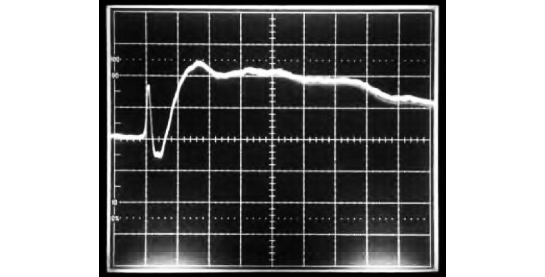
In the Venue article, Fig. 18 (p. 21, see above) shows the step response on a 200μS/div. time scale. The response resembles Fig. 4, second-order all-pass. A second order all-pass is characteristic of a third order CO. While the Venue mid/tweeter CO is electrically second-order, the net acoustic CO is close to third-order.
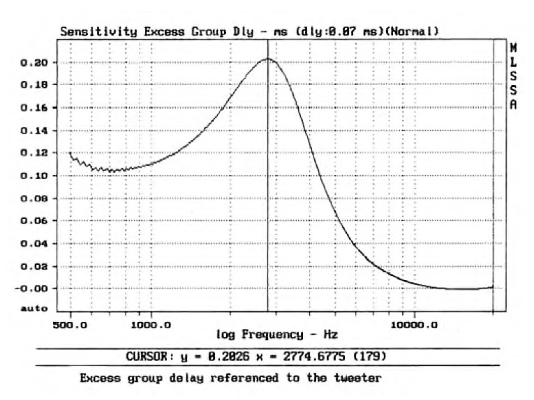
Figure 18 in the Venue article shows about a 200μS delay from the initial tweeter spike to the point where the midrange response reaches the exponential waveform rise time level (63% of steady-state). This agrees with Joe D’Appolito’s excess group delay maximum of 200μS (Venue article, Fig. 14, see above).
My threshold for delay dispersion is about 1mS, so I can’t hear the 200μS mid/tweeter time spread of the Venue. What I found to be important in this CO frequency range (2.5kHz in the Venue) is to have the two drivers’ outputs in phase with each other, around the CO frequency. This is a different thing from absolute waveform phase accuracy. Minimizing inter-driver phase differences at typical tweeter CO frequencies is important for spatial image coherence and sharp focus.
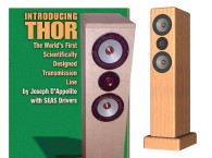
To my ears, a well-designed D’Appolito (MTM) configuration can sound virtually transient-perfect, even with (again, well-designed) high-order COs. I think this is because the symmetrical MTM arrangement makes the midrange and treble acoustic centers spatially coincident. This eliminates the delay-dispersion audibility enhancement with separated drivers that I discussed. The best example I’ve heard is Joe D’Appolito’s Thor speaker (7).
What I Heard with the Ten-Stage All-Pass
With the sawtooth wave around 200Hz, switching in the all-pass dramatically (and I mean that literally) muffled the tone, all but removing the buzzy edge sound. But when I moved the phones 6˝ away from my ears (greatly lowering the SPL but not changing anything in the phones or amp), lo and behold the buzziness returned! Switching the all-pass in and out made no difference.
Effect on Music
This confirmed what I had thought: Although I couldn’t directly hear the 3mS time dispersion strongly (except with xylophones and some drums), I easily heard the ear’s nonlinear reaction to phase shifts. The entire musical sound became “covered,” “veiled,” muted, dulled, and de-focused. With this higher fo of 1060Hz, I needed three all-pass stages to notice the effect. That’s a delay dispersion of 1mS, about the same as my threshold with the lower fo of 232Hz (where one stage has a To of 1.37mS).
All of this establishes (for me) that the phase nonlinearity (time dispersion) of most midrange/tweeter COs is inaudible, while I can hear the bass transient blurring of woofer COs from 100-300Hz if second- or higher-order.
Conclusion
I hope this article has provided some insight into the phenomenon of time dispersion, particularly regarding its audibility (or lack thereof ) in speaker crossover phase nonlinearity. aX
References
1. Dennis Colin, “Waveform Phase Distortion,” Speaker Builder 1/97.
2. Bill Waslo, “Time, Frequency, Phase, and Delay,” Speaker Builder 7/96.
3. John Kreskovsky, “A Transient-Perfect 2nd Order Passive Crossover,” aX May ’01.
4. Dick Crawford, “The Phase Redeemer,” Speaker Builder 5/97.
5. Dennis Colin, “Stereo Subs for the Swans M1,” aX Sept. ’05.
6. Dennis Colin, “The Venue Speaker,” aX Nov. ’06.
7. Joe D’Appolito, “The Thor Speaker,” aX May ’02.
See also: THOR: A D’Appolito Transmission Line
This article was originally published in audioXpress, November 2007.
More on the next page: An Experiment With Higher Frequency Delay Dispersion