Within the audio chain, the loudspeaker could be the element that most influences a user’s auditory experience. A loudspeaker is not only the final element that converts electric input into an audible output, but it is also responsible for an increasing portion of the system’s cost, inefficiency, weight, and size, making it a crucial element for the costumer and the manufacturer.
“Moving coil” (electro-dynamic) transduction has remained the primary method used by loudspeakers since electronic amplification became possible. Even with innovations in material choices, production techniques, and understanding of its intricate behavior, the speaker remains the least efficient segment — in its development and in its use. In its development, the plethora of materials, geometries, designs, and problems can become costly in time and economy. In its use, the speaker taints the output signal with its own characteristics according to its age, size, and material—coloring the spectral content and introducing artifacts or even limiting the acoustic output. The weakest point of most loudspeakers is the low efficiency η0 defined by the ratio between electrical input power Pe and electrical output power Pa in the pass-band as:

where Bl is the force factor, at the voice coil rest position (x = 0); Sd, is the effective radiation area; ρ0, the air density; Re, the DC voice coil resistance; Mms, the moving mass and c, the speed of sound.
For instance, in microspeakers where the force factor Bl and the radiation area SD are small, the pass-band efficiency is below 0.01% generating, for 100 mW input, only 10 μW output. That means these transducers produce more heat than acoustical output. Therefore, the operating voice coil temperature is, in many loudspeakers, close to the permissible threshold and will limit the acoustical output even when using powerful equalization and amplification.
Currently, no alternative transduction principle is mature enough to compete with the conventional moving coil technique. So, it is perceived as the best practice and is improved upon using updated designs and manufacturing methods and materials provided by research.
Loudspeaker performance can be separated into two main behaviors defined by the signal size. The small signal, where the acoustic amplitude is relatively low and the speaker motion is linearly related to the input voltage, and the more interesting large signal performance, where the acoustic amplitude is higher (at a consumer acceptable level) and the individual nonlinear qualities of the mechanical components become more present.
Designing a transducer with its large signal performance in mind is a challenge and requires deep insight of the causes and effects of a loudspeaker’s nonlinear and thermal behavior. Since the 1980s, this topic has attracted the interest of more and more researchers, providing a reliable theoretical framework. The formalization of nonlinear and thermal parameters has opened a new path for loudspeaker diagnostics, as these parameters are able to describe the properties of the loudspeaker itself, independent of the applied stimulus (e.g., a test signal or music). Numerical simulation tools show the relationship between material, geometry, and nonlinear parameters, enabling accurate modeling of both small and large signal behaviors.
The large signal model is able to provide “all state” information, (e.g., displacement and temperature of the voice coil), which could alert in case of mechanical or thermal overload in the transducer. The extended large signal model can be used to predict all state variables and the output signal for an arbitrary input signal. The effect of the nonlinearities and cooling mechanisms can be modeled and analyzed. Design choices can be evaluated before the first prototype is even constructed. Novel auralization techniques make it possible to enhance or attenuate different kinds of signal distortion to assess the audibility and impact on sound quality through listening tests or perceptive models. Closing the link between physical and perceptive assessment opens new ways of defining target performance of an audio product helping develop products at an optimal performance-cost ratio while ensuring acceptable manufacturing quality.
The large signal model is not only the theoretical principle used in transducer development but can also be used in conjunction with digital processing to actively reduce signal distortion and to protect the loudspeaker from mechanical and thermal overload. This paper will provide a short overview on current activities using digital signal processing and on how these could advance this field.
Transducer Modeling
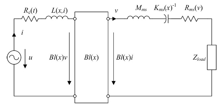
An electro-dynamic transducer using a moving coil in a static magnetic field can be modeled at low frequencies by a network of lumped parameters, where the wavelength is much larger than the size of the transducer (see Figure 1).
The model uses the terminal voltage u, the input current i, the voice-coil displacement x, and the velocity v as state variables. The mass Mms represents the moving transducer parts (cone, coil, suspension, etc.) is considered a constant (linear and time invariant) parameter. The DC voice coil resistance Re(t) is time variant due to its dependence on the voice coil temperature Tv. The load impedance Zload(s) describes the coupled acoustic and mechanic systems. It may be a considered as a time variant parameter due to its sensitivity to changing ambient conditions. The voice coil inductance L(x,i), the force factor Bl(x), the stiffness Kmx(x) and the mechanical resistance Rms(v) are nonlinear parameters that depend on the current state variables, which vary with time due to aging, climate, and other external influences. The nonlinear dependency of the mechanical resistance Rms(v) vs. velocity v can be described as a power series expansion:

where the coefficients rj are time varying parameters. The nonlinear behavior of the mechanical resistance Rms(v) plays an important role in microspeakers where the mechanical losses contribute to the total quality factor. This nonlinearity can be neglected in woofers and subwoofers where the electrical damping is dominant.
The force factor:

the stiffness of the mechanical suspension:

and the voice coil inductance:
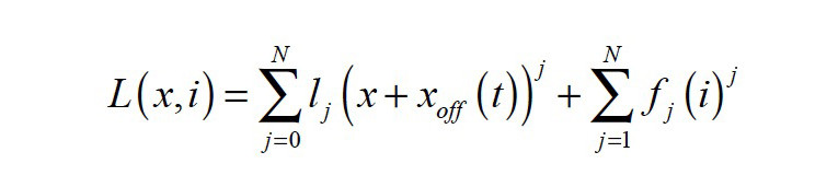
are nonlinear functions of voice coil displacement x(t), current i(t) and voice coil offset xoff(t) from rest position. The offset xoff(t) may be considered as a timevariant parameter as it depends on the interactions between the transducer’s nonlinearities, the stimulus, the suspension’s visco-elastic behavior, gravity, and other external influences. It may also be interpreted as a state variable as it is comprised of only low-frequency components, far below the audio band (f < 20 Hz). By introducing the offset xoff(t), the time variance of the coefficients bi, ki, and li in the power series expansions in Equations 3—5 can be reduced.
Adaptive Non Linear Control
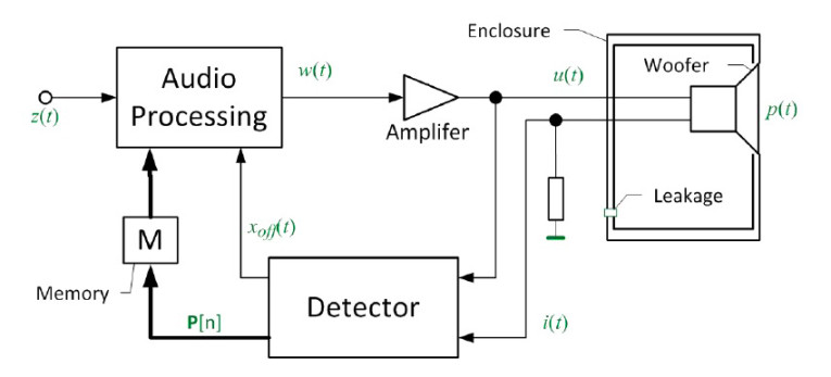
The basic function of the transducer control technique, discussed in my article “Active Compensation of Transducer Nonlinearities,” is illustrated as a signal flow chart shown in Figure 2.
A digital signal processor receives an audio input signal z(t) and generates a control output signal w(t), which is supplied via a power amplifier to the input of any acoustic transducer or any other electro-dynamic transducer. The power amplifier will usually have a low output impedance and use a high-pass filter to avoid driving the transducer with a DC component. A detector will identify the free parameters of a transducer model summarized in a parameter vector P, based on the voltage u(t) and the current i(t) values measured at the transducer terminals.
The parameters in P are assumed to be time-invariant over a limited period (T < 1 min) but will be affected by change in the ambient, aging of the transducer materials as well other changes in the mechanical or acoustical load driven by the motor. For more information, refer to my article “Modeling Load-Induced Aging of Loudspeaker Suspension.”
To cope with these parameter variations, the detector will update the vector P[n] and feed this into to the audio signal processing. Contrary to the negative feedback of state signals, the parameter feedback can cope with any latency caused by DAC, ADC, and other digital signal processing. The latest values in vector P[n] can be stored to use as an initial parameters when restarting the adaptive control system.
The direct measurement of the offset xoff(t) of the voice coil from its rest position will require a mechanical distance sensor (e.g., an optical laser displacement sensor), as the offset cannot be modeled. The detector can identify this offset indirectly by exploiting evenorder nonlinear distortion found in the electrical signals at the transducer terminals. The instantaneous value of xoff(t) is permanently supplied to the audio processing, as illustrated in Figure 2, to cope with a varying voice coil rest position and manage any DC displacement generated by the transducer’s nonlinearities. Updating the value of the offset xoff(t) should be fast to stabilize the voice coil positon for any audio signal.
Parameter Identification
The slower time varying parameters and the offset xoff(t) of the coil’s rest position of the electrical equivalent model summarized in the parameter vector P can be identified by monitoring the voltage and the current at the transducer terminals while the speaker reproduces an audio signal (e.g., music). The parameters are identified by minimizing the error, e(t), produced by the difference between the voltage u’(t) predicted by the model shown in Figure 1 and the measured voltage u(t) in the signal: e(t)=u’(t)-u(t)
Audio Signal Processing
The parameter information (vector P and offset xoff(t)) provided by the detector is used to preprocess the audio signal, generating an improved transducer input signal w(t), protecting the transducer from thermal and mechanical overload to generate the desired overall transfer behavior.
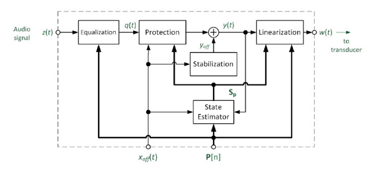
The audio processing comprises different subsystems
connected in series as shown in Figure 3 performing:
• Equalization (alignment) of the amplitude and phase response
• Protection of transducer against overload
• Stabilization of the voice coil rest position
• Linearization of the transfer behavior by compensating nonlinear distortion
The Linearization and Stabilization subsystems at the end of the feed-forward structure generate a defined linear transfer function Hx(s) between control signal y(t) and voice coil displacement x(t) corresponding to the desired linear displacement signal xlin(t).
The predicted voice coil displacement signal can be generated in the State Estimator by a linear filter with the target transfer function Hx(s). The velocity v(t), and the current i(t) can be derived from the displacement x(t). The State estimator subsystem also estimates the increase of voice coil temperature ΔTv based on the variation of the measured resistance Re(t) or the electrical input power Pe supplied to the transducer. All state variables collected in state the vector Sp are supplied to the Linearization and Protection subsystems.

Linearization
The active Linearization of the transducer shown in Figure 3 compensates for the signal distortion and other undesired effects generated by the time variant and nonlinear parameters of the transducer model shown in Figure 1. The voice coil resistance Re(t), the mechanical stiffness Kms(x,t) and the mechanical resistance Rms(v,t) are highly time variant causing significant changes in the resonance frequency, total quality factor and sensitivity.
The nonlinearities cause harmonic and intermodulation distortions, a DC displacement generated by the audio signal’s rectification, and the compression of the fundamental components. The Linearization ensures that the synthesized displacement xlin(t) required in the mechanical protection system corresponds to the real displacement x(t) of the voice coil. Furthermore, the active compensation of the nonlinear distortion improves the quality of the reproduced sound.
The subsystem Linearization performs a nonlinear preprocessing of y(t) generating the control output signal by using information provided by the parameter vector P, xoff, the synthesized state variables SP and the physical relationships provided by the transducer model shown in Figure 1, as described in detail in A. J. Kaiser’s, “Modeling of the Nonlinear Response of an Electrodynamic Loudspeaker by a Volterra Series Expansion”; my “Adaptive Nonlinear Control of Loudspeaker Systems”; and H. Nijmeijer and A.J. van der Schaft, Nonlinear Dynamical Control Systems.
The state prediction and the control law built up a feed-forward structure, which is a mirror image of the nonlinear transducer model, detailed in my article “The Mirror Filter: a New Basis for Reducing Nonlinear Distortion Reduction and Equalizing Response in Woofer Systems.” Figure 4 shows for example the reduction of the second and third-order harmonic distortion of a woofer system with active linearization.
Stabilization
The mechanical suspension determines the voice coil rest position in the magnetic gap. Viscoelasticity and aging of the suspension material, gravity, and other external influences will change the voice rest position over time.
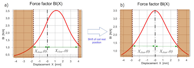
Transducer nonlinearities may cause an unstable behavior of the loudspeaker, moving the coil in a non-predictable way in the positive or negative direction. This offset is not negligible in microspeakers, headphones, and other transducers where no spider is used. It varies the clearance values Xclear- and Xclear+, which describe the maximal displacement to the lower and upper boundaries, respectively, without causing bottoming or generating other kinds of impulsive distortion (rub & buzz). The example shown in Figure 5a reveals a negative offset xoff = –1.1 mm from the original rest position, resulting in a lower force factor Bl(x = 0) at the rest position and an asymmetrical Bl(x) curve generating additional nonlinear distortion. This offset moves the coil closer to the lower boundary reducing the negative clearance Xclear- < Xclear+ and thus, the acoustical output.
Fortunately, the detector provides accurate information of the voice coil offset xoff(t), which can be used to actively shift the voice coil to the optimal rest position in the gap without the need to measure the voice coil’s absolute position by using a mechanical sensor (e.g., a triangulation laser). The subsystem Stabilization shown in Figure 3 generates a DC voltage yoff(t) based on the measured offset xoff(t), which is transferred with the audio signal to the transducer. This approach requires a DC coupled power amplifier.
The active stabilization applied to the transducer shown in Figure 5b moves the coil back to the optimum rest position giving maximum AC displacement due to symmetrical clearance values Xclear- ≈ Xclear+, highest efficiency and minimum distortion.
Protection
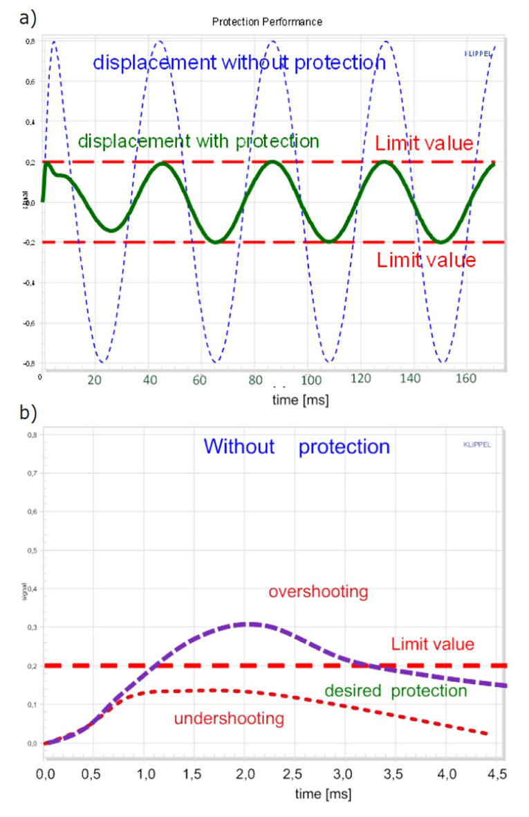
The subsystem Protection compares the voice coil displacement xlin(t) and the voice coil temperature ΔTv with the corresponding protection limits and attenuates the input signal q(t) to prevent a mechanical or thermal overload of the transducer. The protection system should have minimum impact on the reproduced audio signal while keeping the displacement and the temperature just below the critical limits (see Figure 6).
Insufficient attenuation of the audio signal generates a dangerous overshoot over the limits and may damage the transducer. In contrast, an overreaction of the protection system generates an undershoot where the peak values stay far below the permissible limit, which is also undesirable because the acoustical output is more reduced than required to prevent a damage.
The mechanical protection system has to activate the attenuator before the instantaneous displacement exceeds the permissible threshold because the moving mass’s inertia will cause a further rise of the displacement. Mechanical protection systems, which do not increase the audio system’s latency, require an anticipation of the peak displacement by considering the kinetic and potential energy of the mass-spring system, which I discussed further in my paper, “Active Transducer Protection Part 1: Mechanical Overload,” (November 2015).
The thermal protection needs accurate information of the voice coil temperature, which is the transducer part most prone to thermal overload. Temperature monitoring of the magnet is also required in transducers having low thermal capacity, no forced convection cooling or a poor heat transfer to the ambience.
The mean voice coil temperature can reliably be detected by measuring the voice coil DC resistance Re(t) at low frequencies. A pilot tone added to the loudspeaker input is required to keep the measurement operative if the audio signal is muted. Since the pilot tone should be not audible and should only consume a minimum of power, the measurement of the voice coil temperature is relatively slow and cannot cope with short thermal time constants in small speakers having a low thermal capacity. A thermal model of the transducer can predict the variation of the voice coil temperature ΔTv based on input power dissipated in the voice coil resistance Re(t). However, a combination of modeling and measurement necessary.
Equalization
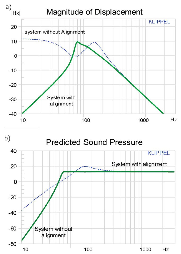
Although the subsystems linearization and stabilization compensate for all the time-variant and nonlinear transducer properties shown in Figure 1, the resulting linear transfer function Hx(s) may not correspond to the desired target behavior. The first subsystem Equalization uses a linear filter and the measured parameter information P describing the transducer as well as potential passive radiator and the acoustical system (ported or sealed enclosure) to align the overall response to the desired target response.
Figure 7 shows the automatic alignment of a ported system to a sixth-order Chebychev target response. The port resonance fp = 72 Hz determines the cut-off frequency of the additional high-pass, reducing the displacement at lower frequencies where the acoustical output is small due to the acoustical cancellation of the volume velocity generated by diaphragm (see Figure 7a). Above the cutoff frequency the stiffness, the mass, and the damping of the transducer are virtually modified by the electric control to provide a flat acoustical response.
Consequences for Transducer Design
The adaptive control can be implemented as software at a low cost if voltage and current signals from the transducer terminals are provided. No additional mechanical or acoustical sensor is required. Adaptive nonlinear control virtually corrects the transfer behavior and generates a desired overall system. Time variance (e.g., aging), production spread and other external influences are automatically compensated. Hence, each audio product has constant properties, which are identical with the prototype over life time. This can also be utilized to provide reliable protection of the transducer against overload for any input signal.
Active linearization of the transducer cannot directly improve the efficiency of the electro-acoustical conversion but it provides new degrees of freedom for passive the transducer and system design. Maximizing efficiency is the most important design goal because it determines acoustical output, amplifier requirements, power consumption, heat development, and battery life time.
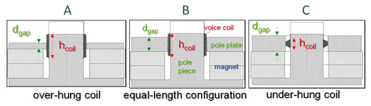
For microspeakers and other transducers operated in the pass band and below resonance, the motor strength defined by Bl2/Re should be a maximum and the moving mass Mms a minimum. The lower cut-off frequency and the overall system’s alignment of the frequency response can be virtually corrected by electrical control. The force factor value Bl(x = 0) at the rest position x = 0 can be maximized by using the motor topology B, shown in Figure 8, where the coil height hcoil approximately equals the gap depth dgap. Here, the coil windings exploit the significant B-field in the gap but a small coil displacement moves already some windings out of the gap and reduces the force factor value Bl(x).
The overhang coil topology A on the right hand side with hcoil > dgap has got additional spare windings below and above the gap which enter the gap with the displacement x. This improves the linearity of the force factor Bl(x) in the plateau region defined by |x(t)| < (hcoil – dgap)/2 but the additional spare windings increase the moving mass Mms and the electrical resistance Re, and thus, reduce the efficiency defined in Equation 1. The under-hang topology C with hcoil < dgap also provides an almost constant force factor value for |x(t)| < (dgap – hcoil)/2 but the linearity reduces efficiency at the rest position x = 0 because the larger gap depth dgap reduces the induction B in the gap.
The efficiency defined by Equation 1 describes the transducer’s efficiency in the small signal domain where the force factor value is constant and the nonlinear control is not active. We also need to describe the transducer’s efficiency in the large signal domain.
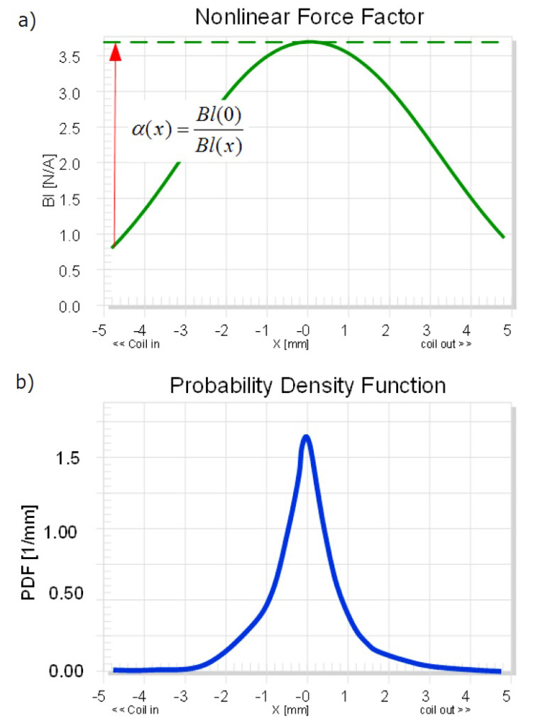
The equal-length topology B, shown in Figure 8, provides the highest efficiency for reproducing music, speech, and other audio signals in the small signal domain. In the large signal domain, the instantaneous voice coil displacement reduces the Bl(x) temporarily (see Figure 9a). Active linearization is required to increase the input signal by a control gain α(x) to virtually generate a constant transduction factor, shown as dashed line in Figure 9a.
Portable applications where power consumption and battery capacity is an issue will require transducers with the highest efficiency and minimum use of natural resources (e.g., neodymium-magnet and energy). Such a highly efficient speaker is typically nonlinear using a motor topology where the voice coil exploits the magnet field in the gap and gives the highest force factor value Bl(x) at the rest position x = 0. Unfortunately, the varying force factor Bl(x) generates significant intermodulation distortion throughout the audio band if the voice coil is displaced and windings are leaving a gap. This undesired side-effect of the efficient motor structure can be compensated by an inverse nonlinear preprocessing of the electrical input signal, which was discussed in H. Nijmeijer and A.J. van der Schaft’s book, Nonlinear Dynamical Control Systems (Springer, 1990). The pass band efficiency of the transducer operated in the large signal domain can be expressed as:

by using the probability density function pdf(x). The integral may be interpreted as an effective value of the squared force factor considering the distribution of the excitation signal. Figure 9b shows the pdf(x) of a woofer’s voice displacement reproducing popular music. Most of the time, the voice coil is close to the rest position x = 0 and the maximum peak displacement occurs less frequently. Thus, the equal-length topology B, shown in Figure 8, actively linearized by adaptive control, gives the highest efficiency both at small and high amplitudes if common audio signals with a similar pdf(x) are reproduced. The linearization will not change the amplifier requirements if not more than 50% of the voice coil wire moves out of the gap and the control gain α(x) < 2 will not significantly increase the peak voltage and peak current of the electric input signal.
The efficiency of a transducer at frequencies f below the natural resonance frequency fs becomes important in active loudspeaker systems, which use a small sealed enclosure and equalization to extend the usable bandwidth to lower frequencies by a “bass boost.” The efficiency can be expressed as:
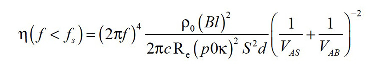
with the static sound pressure p0, the adiabatic coefficient k and the equivalent air volume VAS, corresponding to the compliance of the mechanical suspension, which is usually larger than the enclosed air volume VAB. The efficiency can be increased by making the mechanical suspension more compliant and by reducing the size of the effective radiation area SD while increasing the peak displacement of the transducer to generate the desired maximal acoustical output. This puts higher demands on the motor structure’s design and the mechanical suspension, and requires adaptive nonlinear control to stabilize the voice coil rest position and to prevent mechanical overload.
Conclusion
The amalgamation of signal processing, power amplification with current and voltage monitoring, and transducer design leads to a new generation of loudspeaker systems generating more output at higher efficiency with higher sound quality while using less weight, size, and cost. The loudspeaker system permanently monitors the transducer’s electrical, mechanical, acoustical, and thermal states and uses this information for the audio signal processing to generate the desired transfer behavior and to protect the transducer against mechanical and thermal overload. The system uses the electrical signals at the transducer terminals to identify all parameters and state variables of the nonlinear transducer model.
The identification is performed as an adaptive process to simplify the tuning to a particular device and to cope with time variance of the transducer properties (e.g., due to aging). The active protection in connection with nonlinear control (e.g., linearization and stabilization) makes it possible to operate the transducer close to the physical limits without generating a damage or excessive distortion. The control system can automatically equalize the loudspeaker system to a desired target response while using the transducer and enclosure parameters identified by the control system itself without using a loudspeaker expert. The active stabilization of the voice coil rest position using a DC coupled amplifier copes with production spread and aging and opens new possibilities for more compliant suspension systems. The control algorithms use the large signal transducer model and identify the parameters adaptively. By merging electroacoustics and signal processing the loudspeaker becomes a self-learning system providing optimum performance over the lifetime of the audio product. VC
This article was originally published in Voice Coil, May 2016.
Resources
1. A. J. Kaiser, “Modeling of the Nonlinear Response of an Electrodynamic Loudspeaker by a Volterra Series Expansion,” Journal of the Audio Engineering Society, 35, p. 421, June 1987.
2. F. Agerkvist and T. Ritter, “Modeling Viscoelasticity of Loudspeaker Suspensions Using Retardation Spectra,” 129th Convention of the Audio Engineering Society presentation, 2010.
3. Klippel Tutorial: “Loudspeaker Nonlinearities: Causes, Parameters, Symptoms“ Journal of the Audio Engineering Society, 54, No. 10, October 2006.
4. W. Klippel, “Modeling Load-Induced Aging of Loudspeaker Suspension,” Proceedings of the Acoustics 2012 Nantes Conference, April, 2012, Nantes, France.
5. ———, “Active Compensation of Transducer Nonlinearities,” 23rd International Conference of the Audio Engineering Society, May 2003.
6. ———, “Adaptive Nonlinear Control of Loudspeaker Systems,” Journal of the Audio Engineering Society, 46, 1998.
7. ———, “Direct Feedback Linearization of Nonlinear Loudspeaker Systems,” Journal of the Audio Engineering Society, 46, 1998.
8. ———, “The Mirror Filter: a New Basis for Reducing Nonlinear Distortion Reduction and Equalizing Response in Woofer Systems,” Journal of the Audio Engineering Society, 32, Heft 9, S. 675-691, 1992.
9. ———, “Adaptive Stabilization of Electro-Dynamic Transducers,“ Journal of the Audio Engineering Society, Vol. 63, No. 3, March 2015.
10. ———, “Active Transducer Protection Part 1: Mechanical Overload,” 139th Convention of the Audio Engineering Society presentation, October 2015.
11. M. H. Knudsen and J. G. Jensen, “Low-Frequency Loudspeaker Models that Include Suspension Creep,” Journal of the Audio Engineering Society, vol. 41, pp. 3–18, January/February 1993.
12. H. Nijmeijer and A.J. van der Schaft, Nonlinear Dynamical Control Systems, Springer, 1990.
13. J. Suykens, J. Vandewalle and J. van Gindeuren, “Feedback Linearization of Nonlinear Distortion in Electrodynamic Loudspeakers,” Journal of the Audio Engineering Society, Vol. 43, No. 9, 1995.
www.klippel.de