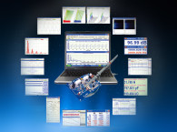
 In this article series, we are examining ways to create a low-cost system for lab-grade audio electronics measurements. Thus far, I hope the first three articles in this series have whetted your interest in inexpensively extending your measurement capabilities. Now, we must select the right interface.
In the first few installments of this series, I looked at the basic hardware and software aspects of using computer sound cards for audio measurements. The goal is to create an inexpensive (less than $200 or so) system that can do a variety of audio measurements, which was previously the exclusive dominion of expensive test gear (e.g., distortion meters, spectrum analyzers, and impedance bridges).
Thus far, I have provided an overview starting with the computer, moving on to the sound card, and some of the software options. Now, we’re only a step away from the lab bench, so let’s consider the crucial part where the metaphorical rubber meets the road — the interface to the device under test (DUT) that you want to characterize (e.g., an amplifier, a phono cartridge, a CD player, or a loudspeaker).
How do we get the sound card and the DUT to “talk” to one another? The sound card will likely have an input impedance of 10 kΩ or so. It will also have an input and output voltage capability of 2 V or so. The former means that measurement of any circuit with a moderate or high impedance will be loaded down by the sound card (and the cable connecting it to the sound card) and give inaccurate values. The latter means that low-voltage measurements will be compromised by noise, high voltage measurements will overload the inputs and potentially damage the sound card, and low impedance loads or loads that require significant voltage drive will cause the sound card to prematurely stop working.
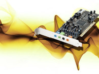
Audio Interfaces
These limitations aren’t as onerous as they might seem at first glance. We can certainly measure preamps, DACs, CD players, and similar line level components without much fuss. Since these are levels comparable to a microphone preamp output, we can also do loudspeaker frequency response measurements without difficulty. But, what about power amps? High impedance circuits? Phono cartridges?
Traditional instruments (i.e., oscilloscopes, spectrum analyzers, distortion analyzers, wave analyzers, and AC voltmeters) typically feature high impedance (1M or higher) to avoid loading down higher impedance circuits. For different voltage levels, there is generally a stepped attenuator to specify the voltage range, so the instrument has the ability to measure signals in the microvolt range, and then with the twist of a knob, hundreds of volts.
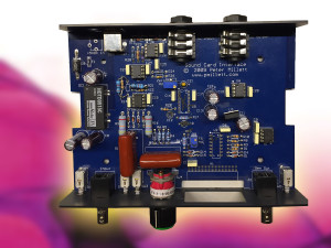
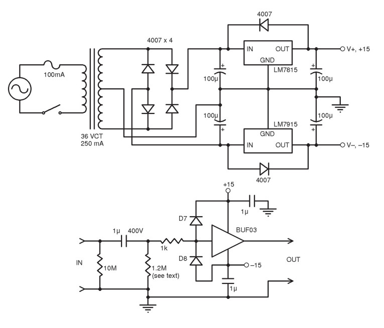
We can add some of these features directly to the sound card measurement system by setting up external jigs. Figure 1 shows the schematic for one that I have already built. It is a unity gain single ended circuit with a 1-M input impedance. The input is capacitively coupled so that DC will not affect the performance of the jig or—in the case of voltages commonly found in tube circuits—burn out the jig and/or the sound card. In my usual low-rent fashion, I built it using point-to-point wiring on a perfboard inside an inexpensive RadioShack project box. I built this as a two-channel device. Typically, I use one channel between the DUT and the sound card’s input, since the jig’s 1-M input impedance significantly reduces the loading on the DUT compared to the 10 to 20 kΩ of the sound card’s direct input. I use the other channel when I need to drive a low-impedance load or one with significant capacitance where the sound card output might be compromised.
The buffers I used (BUF03) are no longer available, but there are several newer parts that will give equivalent or even better performance. You’ll want a buffer with low-bias current to successfully keep the input impedance high. An excellent example is the EL5x23 series from Intersil, which has lower noise than the old BUF03s in my interface box.
The Intersil part does not have the BUF03’s current capability, but with a 30-mA drive available, it should be sufficient for most applications. If you need more drive (e.g., for applying signal to a highly capacitive load), you can use the EL5x23 to drive the input of a Linear Technology LT1010 buffer. The LT1010 buffer has 150 mA of drive capability, but high input bias current, so its input needs buffering to maintain a high input impedance. If you’re using a low-impedance source and don’t care about having a high input impedance (e.g., for being driven directly from a sound card output), you can substitute the LT1010 into my circuit by changing the input resistor from 1M to something between 2 kΩ and 4.7 kΩ.
In either case, the output impedance of the buffer will be quite low — the BUF03 is 2R, the LT1010 is 5 to 10R, and the EL5x23 is not specified. However, my measurements suggest that it’s under 5R. If you require a higher source Z for a measurement, like 600R for studio equipment, a resistor can be tacked in series with the output. That’s the one advantage of the DIY construction that I used compared to a nice PCB—it’s easy to add temporary parts for measurement.
For oscilloscopes (and of ten the other instruments), the capacitive loading of a circuit by the test cable to the instrument, which can run in the hundreds of picofarads, can be reduced by using a 10x scope probe. This decreases capacitance to a few picofarads but drops the measured voltage by a factor of 10. Those probes aren’t just limited to oscilloscopes — they also can be connected to this interface. The probe will expect the loading of the interface box to be 1M, so this is why that value was chosen. The 10x reduction in measured voltage is acceptable for larger signals and can, in fact, extend the range of measurement for the sound card to 20 V or so. Likewise, you can also buy x100 probes, which will enable you to measure to 200 V. Again, the load on the instrument end of the probe needs to be 1M, so an interface box like mine is a must. And BNC connectors are standard for this application.
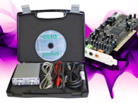
Millett’s Interface Box
If you prefer a more convenient, more versatile, neater, and lower noise solution (the BUF03 is not very quiet), Pete Millett has designed a nice interface box with switchable voltage range from 200 mV to 200 V, a built-in AC voltmeter, and a choice between single-ended and quasi-balanced inputs and outputs. The interface either amplifies or attenuates the signal so that the sound card is presented with a 2-V signal at the maximum of the selected range of the interface. It uses 0.25” stereo phone plugs for balanced connection to the sound card input and output, and BNC plugs for the DUT’s signal output and input. Power is taken from the computer’s USB port.
One issue I have with the Millett interface is that its input impedance is 100 kΩ rather than the 1M I would prefer. Millett’s logic is that higher input impedance could potentially lead to more noise. I am unconvinced since his chosen input amplifier is the OPA2604, which has extremely low input current and current noise. Likewise, the input impedance is shunted by the DUT’s source impedance, so that would be expected to reduce the effect of the input impedance on the interface’s noise. If you do what I suggest (and Millett has updated his webpage to mention it, along with his reasons for not recommending it!), increase the values of R4 through R7 by a factor of 10.
As a practical matter, when I did this, I couldn’t see any significant increase in noise. And the 1 M input impedance enables us to use the 10x probes with a greatly reduced capacitive loading on the DUT. If you think all your measurements will be of low impedance sources, use Millett’s specified values. Remember that using the 10x probe will change the voltage ranges shown on the selector switch and AC voltmeter by a factor of ten. The balanced outputs are provided by DRV134 differential line drivers, so the source impedance is about 50R and current drive is up to 50 mA.
As with any sort of measurement, grounding of the measurement interfaces, sound card, and DUT can be a bit of trial and error. I found that if I powered the interface from a battery pack, I had an easier time avoiding ground loops and noise. A stack of four D batteries gave me 6 V at the power input, and my test setups became much quicker to optimize.
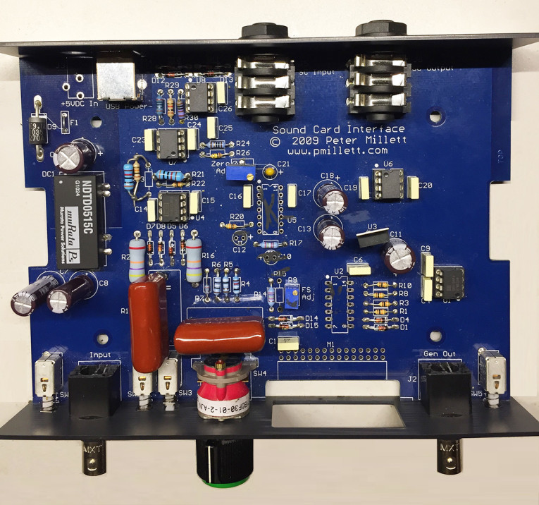
All in all, I would strongly recommend starting out with Millett’s interface for speed, flexibility, and expediency. If it had been around 10 years ago, I probably wouldn’t have bothered building my own. If you’re ambitious, you can play around with upgrading the op-amps and line drivers, altering some of the grounding, and building a battery pack, but that’s somewhat gilding the lily. My own build of this box omitted the internal voltmeter, which made the construction a very inexpensive proposition (see Photo 1).
A Question of Balance
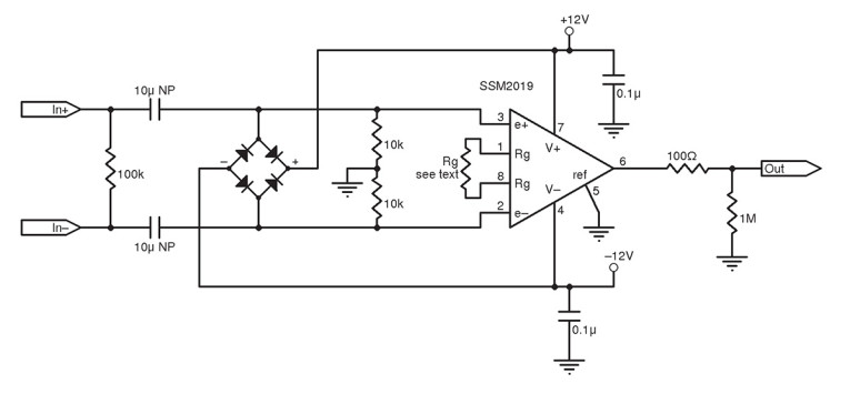
Measuring small signals is even more of a challenge. Noise pickup and gain are the key issues. Analog Devices (ADI) has come up with a terrific solution aimed toward the microphone market — the SSM2019 balanced input audio preamplifier. This chip can run balanced or unbalanced inputs (which is useful if your sound card only has single-ended inputs). The chip also has impressive common-mode rejection and can be varied in gain from 0 dB (unity gain) to 60 dB (gain of 1,000) by selecting a single resistor. It has a single-ended output and boasts outstandingly low input voltage noise (about 1 nV/rt Hz).
This is perfect for looking at the output of a microphone or phono cartridge — a 10R gain setting resistor will give a gain of 1,000, which is suitable for most applications like this. For other gains, use the resistor values recommended on the SSM2019 datasheet (see Resources).
Figure 2 shows the circuit I used. The diode bridge at the input is for overvoltage protection. The type of diode used is noncritical, but try to find one with relatively low leakage and reverse capacitance. I used UF4007 because I had a drawer full of them. The power supply is also noncritical. As before, I used batteries to prevent any possible ground loops. I also built my unit on perfboard and housed it in a small project box. The input connector choice is yours. For convenience, I used XLR connectors. I plan to use this interface in some demonstration measurements discussed in a future article in this series.
Things to Come
Next month, we’ll delve into a bit of the basic math to understand Fourier Transforms at a level that will enable us to choose appropriate software settings for good distortion and frequency response measurements. ax
Resources
Analog Devices, Inc., “Self-Contained Audio Preamplifier, datasheet, 20111,
www.analog.com/media/en/technical-documentation/data-sheets/SSM2019.pdf
Intersil, “12 MHz 4-, 8-, 10- and 12-Channel Rail-to-Rail Input-Output Buffers,” datasheet, 2010,
www.intersil.com/content/dam/Intersil/documents/el51/el5123-223-323-5423.pdf
Linear Technology Corp., “LT1010,” datasheet, 1991,
http://cds.linear.com/docs/en/datasheet/1010fe.pdf
P. Millett, “Sound Card Interface,” www.pmillett.com/ATEST.htm
Sources
SSM2019 Audio preamplifier - Analog Devices, Inc. | www.analog.com
EL5x23 series - Intersil | www.intersil.com
LT1010 buffer - Linear Technology Corp. | www.linear.com
OPA2604 Op-amp and DRV134 differential line driver - Texas Instruments, Inc. | www.ti.com
This article was originally published in audioXpress, September 2015.
Read Part 1 | Read Part 2 | Read Part 3