Loftin-White Circuit
I discovered the Loftin-White circuit while I was looking for a simple single-ended tube (SET) design of a high-quality valve amplifier based on a 2A3 direct-heated triode (DHT) vacuum power tube.
This circuit’s roots date back to 1929. The first information concerning the Loftin-White circuit was published by E. H. Loftin and S. Y. White in the American magazine Radio News. Loftin and White wrote of an amplifier design, with a direct-coupled circuit. There was no capacitor or coupling transformer between the driver and the power stages. For the record, the “Loftin-White” prototype amplifier containing this circuit design used the 224 tetrode in the driver stage and the 250 triode in the power (output) stage.
The direct-coupling circuit seems easy to implement, but it is not. These circuits enable DC and AC signals to be passed to the power gain stage’s grid because there is no coupling capacitor in the signal path. That is the point that affects the sound quality (e.g., big sound stage, rich musicality, and transparency).
On the other hand, the existence of noise (e.g., hum and RF that pass to the final gain stage) also affects the amplifier’s sound and produces noise or a harsh sound. To eliminate these problems, I worked with the same parameters in both channels. I used matched pairs of driving and output tubes, with exactly the same adjustments, careful biasing, and only high-quality materials.
Circuit Construction - Tubes and Biasing
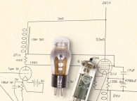
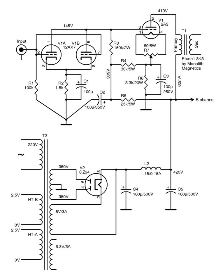
I chose the 2A3 directly heated triode power tube to implement the Loftin-White circuit. The 2A3 vacuum tube is a power triode capable of outputting 3.5 W in a single-ended Class A configuration. In this project, the 2A3 power tube runs at a 60-mA plate current with no signal applied and has a 410-V plate voltage. The output transformer’s primary impedance is 3.3 kΩ (see Figure 1).
Because the 2A3 tube is a directly heated triode, the cathode and filaments are connected, so the design must avoid hum. For this reason, the 2A3 filaments/cathode are connected directly to the hum control potentiometer’s resistive elements. This 50-Ω/5-W potentiometer acts as an attenuator for hum elimination. The potentiometer’s wiper is directly connected to the heavy-duty, good-quality cathode resistor. This resistor sets the current through the power triode. The 3K3 cathode resistor sets the current at about 59 mA. I bypassed the cathode resistor with a 100-µF/250-V high-quality audio electrolytic capacitor.
The driver stage uses a high-gain 12AX7/ECC83 dual triode that operates as a grounded cathode amplifier. The dual-triode grids are connected directly to the signal input. The input impedance is 100 kΩ. Driver tubes are cathode biased with a 1.5-kΩ resistor, and 145-V plate voltage. To bypass the cathode resistor, I used a quality audio electrolytic capacitor. The output is taken from the triode plates directly to the power tube’s grid.
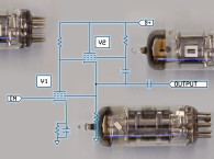
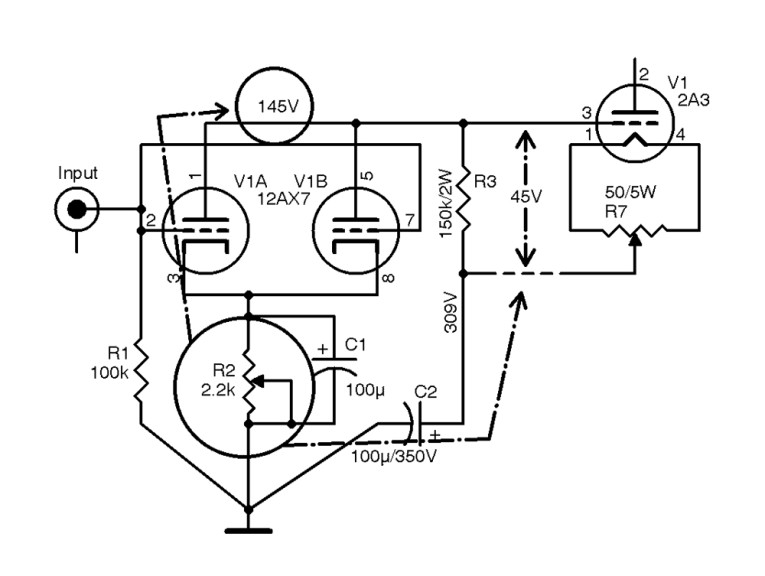
In direct-coupling circuits, both channels must be perfectly balanced (in voltage terms) for better sound performance. Because each tube has different characteristics (even in matched pair tubes), one can easily fine-tune the driving tubes’ plate voltage and the power tubes’ grid voltage by changing the cathode resistor’s value.
To achieve that, a 2.2-kΩ trimmer can be connected to the 12AX7 tube’s cathode (see R2 in Figure 2). The 12AX7 plate voltage can be adjusted so the 2A3 tube’s grid-to-cathode voltage reaches 44 to 45 V. Once the grid-to-cathode voltage reaches 45 V, the cathode resistor is measured with the trimmer value, and it is replaced with an equal-value resistor (see Figure 2). I must mention that if the driver tubes are removed while the amplifier is in use, or the driver tube fails, the output tube can easily lose its bias voltage because there is no coupling capacitor in the signal path.
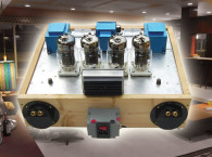
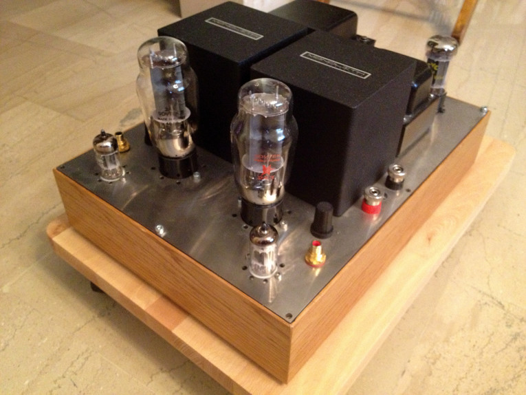
For this project, I chose a matched pair of Sovteks 2A3 power tubes and a matched pair of Electro-Harmonix 12AX7 (see Photo 2). I also tested the amplifier with a pair of new old stock (NOS) Philips ECC83 tubes (see Photo 3). For the power tubes I would likewise recommend the “Emission Labs” EML 2A3 (a matched pair). A pair of WBT RCA jacks is used in the signal input section.


The Power Supply
While designing a hi-fi tube amplifier, you must carefully select the power supply. High-quality parts in the power supply are the key to success. I used an E-shaped, custom-made power transformer (see Photo 4). It had the following windings:
Primary winding: 230 VAC (110 VAC for US)
Secondary windings: 6.3-V/3-A filaments for 12AX7 tubes
2.5-V/4-A filaments for 2A3 tube/channel A
2.5-V/4-A filaments for 2A3 tube/channel B
5-V/3-A filaments for GZ34
350 V-0-350 V/200 mA
The power supply’s output voltage always decreases as more current is drawn. This happens not only because of the increased voltage drops in the transformer and filter chokes, but also because the output voltage tends to reach the transformer voltage’s peak value as a result of the first capacitor charging. Proper filter design can eliminate this effect.
In this project, the rectifier circuit uses a single section “pi” filter or a “capacitor-input filter” with no need for a bleeder resistor. Filter capacitor C4 and smoothing capacitor C5 are 100-µF/500-V JJ Electronic electrolytic capacitors. I used a 15-H/150-mA custom-made choke. The B+ voltage is between 420 and 430 V. The power tube’s filaments are powered with 2.5 VAC and the driving tubes’s filaments are powered with 6.3 VAC.
The rectifier bridge circuit in the power supply section uses the GZ34/ 5AR4 full-wave rectifier. I obtained excellent filtering results when I combined them with a pair of electrolytic capacitors (JJ Electronic or Mundorf). I also used a filtered International Electrotechnical Commission (IEC) power input connector with an embedded power switch.

Output Transformers
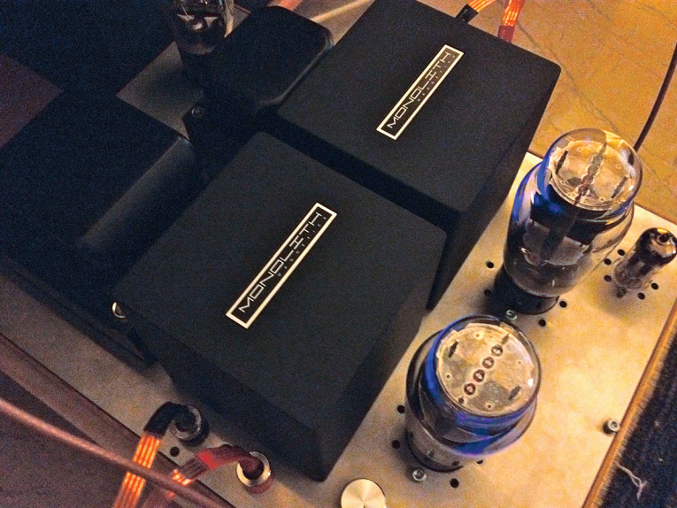
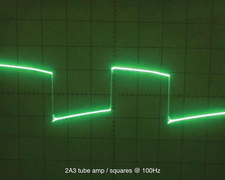
The most critical component in the sound path is the output transformer. Therefore, you should never compromise on the output transformers’ quality. I used a Monolith Magnetics ETUDE1 series high-quality, single-ended output transformer for this amplifier. A high-grade grain SiFe dual C-core is at the heart of any Monolith transformer (see Photo 5). The resonance-free frequency range is much better than 7 Hz to 75 kHz (–3 dB).
Due to their excellent quality, the result is fast transients, live voices, and exceptional low, mid, and high frequencies (see Figure 3).
Electrical data of monolith magnetics Etude1 output transformer includes:
Primary impedance: 3,300 Ω
Secondary load impedance: 4 and 8 Ω
Winding ratio (4 and 8 Ω ): 29.04/20.66
Bandwidth (–3 dB at 1 W, secondary grounded): 7 to 98,000 Hz
Core saturation: 22 Hz at 10 W RMS
Primary inductance: 25 Hz
Leakage inductance: 11 mH
Shunt capacitance secondary grounded: 632 pF
Shunt capacitance secondary floating: 393 pF
Primary DC resistance: 155 Ω
Secondary DC resistance (4 and 8 Ω): 0.208 and 0.420 Ω
Insertion loss (4 and 8 Ω): 0.41 and 0.41 dB
Assembly and Completion
The chassis is constructed from 1.5-mm-thick stainless steel. I designed and the chassis on the computer and used a laser-cutting CNC machine for the cutting work. Laser cutting is ideal because the results are precise. The edges are burr free with minimal gaps and the cutting process has no impact on the base material’s rigidity.
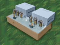
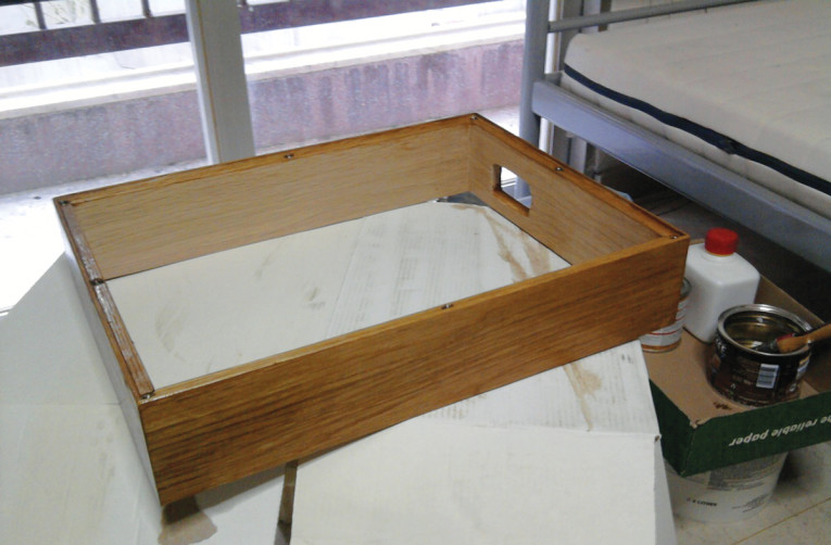
The wood casing (oak or cherry) is individually handcrafted (see Photo 6). All soldering underneath the CNC-machined chassis is handmade, point-to-point wiring. All tube sockets are made of high-quality porcelain.
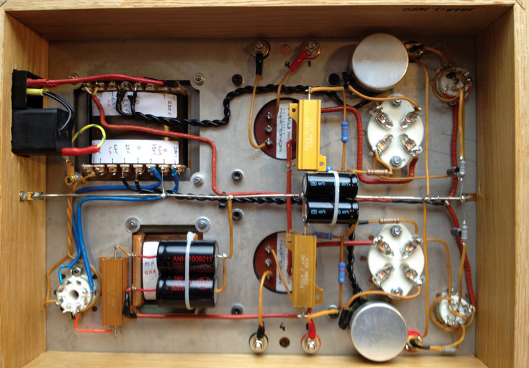
First, I installed all the chassis’s basic components (e.g., the tube sockets, the output transformers, the power transformer, the choke, the RCA jacks, the speaker jacks, etc.). Then I finished the basic wiring, starting with the filaments. I used 1.3-mm (AWG 16) silver wire for the ground plane line and for all critical paths. Next, I soldered all the parts directly from tube sockets to hard-wire lines (see Photo 7). Because of the small number of parts, there is no need to use any soldering tag board. In the final step, I mounted the assembled CNC chassis to the wood casing. The stainless steel chassis fits into the wooden case.
Listening Impressions
With 3.5-W output power, this amplifier loves horn-based speaker systems. In my 6.4-m long × 3.4-m wide listening room, I deliver an enormous sonic picture, driving my back-loaded horn speakers. The amplifier reveals a magnificent sound stage with warm sound and pleasant harmonics. So, if you want to drive full-range or horn speakers, this is the right amplifier. aX
Resources
A. Ghirardi, “An Elementary Text Which Explains the Principles of Electricity and Radio,” Radio Physics Course, Farrar & Rinehart, Inc., 1942 - www.radiomuseum.org/forum/loftin_white_amplifier.html.
Monolith Magnetics, www.monolithmagnetics.com.
RCA Receiving Tube Manual, Technical Series RC-19, RCA, 1959.
This article was originally published in audioXpress, August 2013