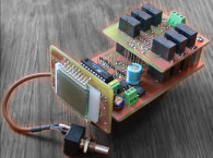
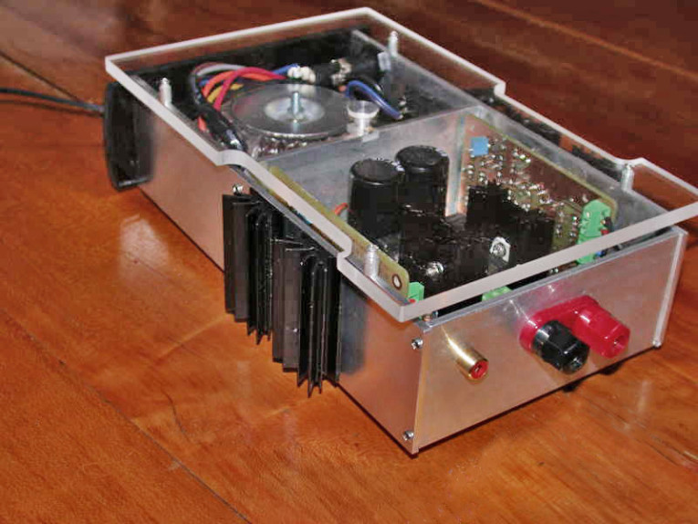
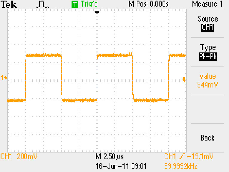
What you do get in spades is accuracy and an ability to drive difficult loads well. The Burr-Brown HA-5002 (see Photo 1) is a gem that I have used in several audio designs in both preamps and power amps. Why not? It has a slew rate of 1300 V/μs. Figure 1 shows one block’s square wave output, not at 10 kHz but 100 kHz. The 1 MHz trace is as equally impressive. Try and accomplish that with an op-amp!
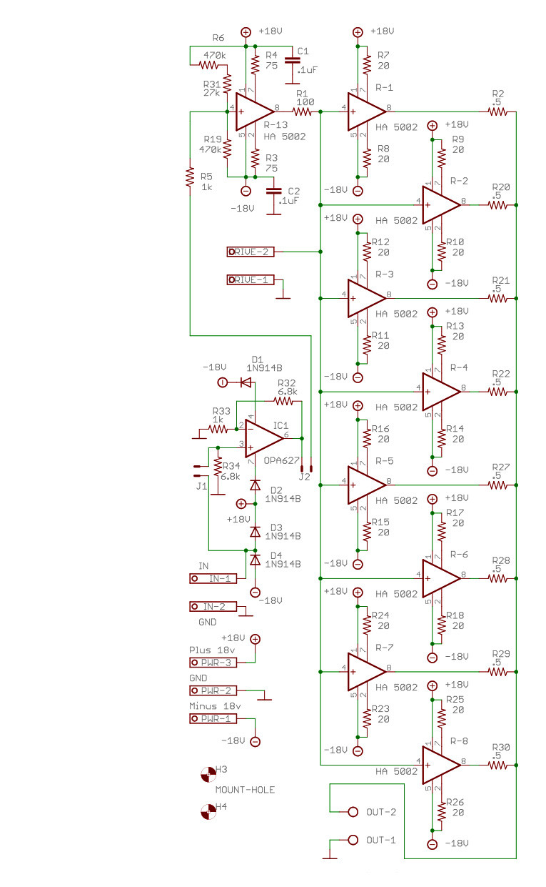
This is a current amp (ie., the gain is unity), but I added the ability to jumper in an op-amp for gain (see Figure 2). Why make the whole amp out of slow poke op-amps when all we need is one? Besides, I like to control amplification in my preamps where I can contour and control the delicate signal and not in the power amp where I want brute force to drive dynamic loads. Do we really need another 20 dB of gain in the power amp after we already have 20 to 25 dB of gain driving it?
While I added op-amp ability, I personally don’t use it. This amp sits in my office and is run by my 20-db gain preamps streamed from my computer, CD player, and an analog tuner. What I did add is a powered subwoofer because I think two-way speakers with a subwoofer make the best sound. What I will add to the system is my venerable AR turntable and an MC cartridge. When I do, I’ll build an MC amp. I tried the popular OPA227 and, with its better specs, the OPA627. Neither sounded bad, but I prefer my own JFET and 6SN7 tube preamps. They put out a sound I really enjoy for hours on end.
The Circuit
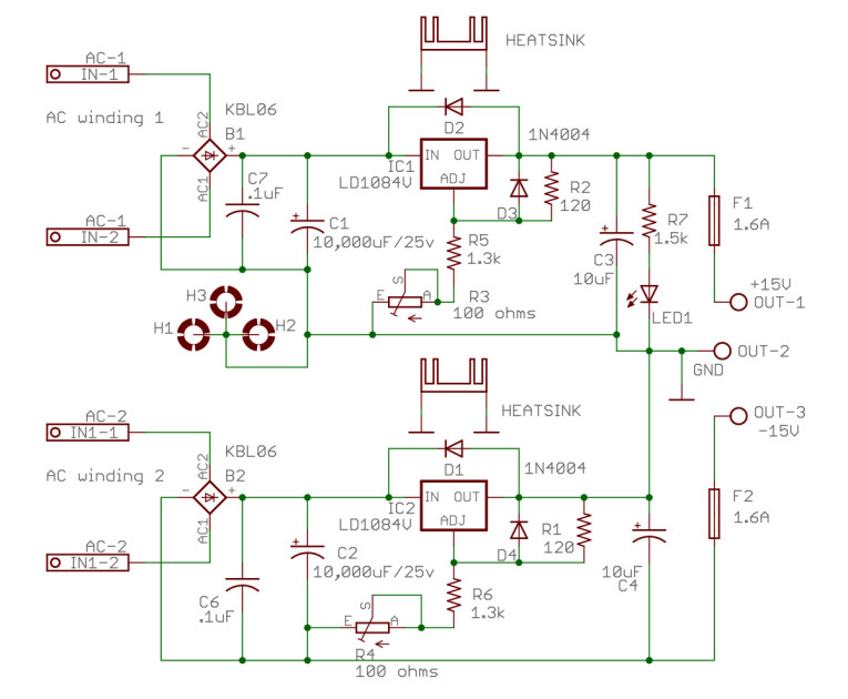
The power supply is straightforward. It runs two LM1084-5A regulators, each controlled by a multiple-turn pot (see Figure 3). (I like to balance my buffers with exactly the same ±voltages.) Voltage drop at full power is low driven from a dual output torroidal transformer. You do not have to use a torroidal transformer, in fact, two 15- to 18-V transformers will work fine, although likely take up more space. Just make sure to keep the transformer away from signal paths. The best solution is a dedicated power box.
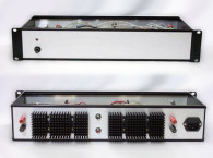
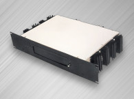
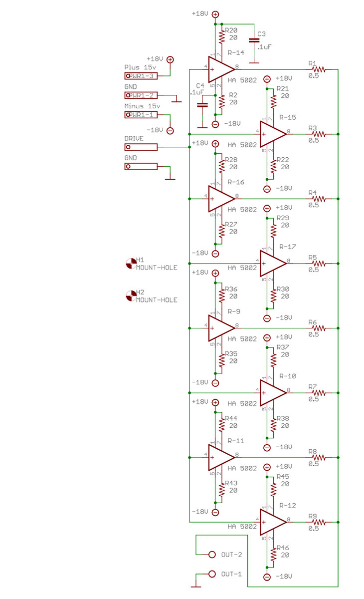
The amplifier can be built to suit your needs. Running with only the drive board and four or eight 5002s in one case will give you a small footprint for tight spaces and nightstands. You can reduce the power supply accordingly. The op-amp choice is yours. I tested the circuit with an OPA227 and an OPA627, but others will work fine. Because they max out at ±18 V, I used two silicon diodes to drop the ±18-V supply 0.7 V on each leg for op-amp safety. To incorporate the op-amp into the circuit, place two jumpers on the four pins, one jumper on J1 and the other on J2. To use the amp without the op-amp, place one jumper on the two middle pins. That’s it; nothing else is required. In fact, I tested the amp in both configurations switching between the two often in a matter of seconds.
D3 and D4 keep the input signal from exceeding the power supply voltage and, thus, the input levels. The 0.5-Ω resistors on the outputs of each 5002 prevent hogging, but I ran this amp without them for a year with no problems, even so damping is quite good with them in or out. The 20-Ω current-limiting resistors save the chips, but a short on the output will blow the two 1.6-A power supply fuses before any damage is done.

Building and testing
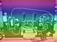
I have worked to keep this design within the scope of most builders. There are no SMD devices, and the boards go together well. Figure 4 shows how to heatsink the 5002s. It works very well and by cutting standard heatsinks in half or using a thick aluminum case as the heatsink this amp will run very cool. The trick to get all the chips to touch the heatsink equally is to place all the sockets on the board loosely and then place a book or flat object on top of the sockets. Now, turn the complete board and flat surface over as one unit so that the board bottom faces up. Then, solder all the sockets into place.
What the builder should pay very close attention to is testing. One solder short can destroy all the chips in a few seconds. Before any chips are inserted in their sockets (I prefer using sockets), power up the board and check pins 1 and 7 of the 5002s for +18 V. Once this is verified, check pins 2 and 5 for –18 V. On the main board, with power off, place one lead of an ohm meter on pin 8 of the drive 5002 (#1) and then check every other 5002 for 100 Ω on pin 4 with respect to pin 8 of the main drive chip. This is important because the drive chip keeps the bias of the chips at near 0 V. (Bias should be within 100 mV, my amps run about 10 to 20 mV max.)
Next, check again with the power off, from pin 4 to pin 8 on each chip. This should be an open circuit. On board two (the one without the drive chip), check from the input drive pin to pin 4 on each chip (see Figure 5). This should be a dead short.
Once all these test pass, place the 5002 drive chip in and one other 5002, power the amp up, put a 10-kHz signal on the input (make sure one jumper is on the two inner pins), and check the output for the identical signal. After this passes, place half the output chips in and retest, place the final chips in, and test again.
Finally, place an op-amp in its socket place jumpers on the outside pins. You should see the input signal with the gain you have chosen. I set the gain at 6.8, but you can change the 6.8-kΩ resistor to a higher value to get the gain you want (e.g., a 10-kΩ resistor will give you 20-db gain or a voltage gain of 10). Don’t go lower. Some chips don’t work well under a gain of 5.
This amp is quite remarkable. As I said, I use it with my JFET and tube preamps without any harshness. In fact, it takes on the character of the preamp, which is exactly what I’m looking for. It will embarrass poor music and poor preamps with its accuracy. It will reward solid designs and quality speakers with an exceptional sound that has exceeded most of the small amps I’ve heard.
Specifications
A word about the specs. Distortion weighs low on my scale. As I’ve said, often no one can hear the difference between 0.05% and 0.001%. I’ve heard wonderfully musical amps that have 0.5% distortion (both tube and solid state). So, when I check specs, if the distortion and noise are below 0.1%, I don’t pay much more attention to them. Rise time is another issue, and I can hear this characteristic.
I get weary of amps that have poor rise times. Orchestras get muddy and harmonics blur, guitar music bloats and loses clarity. This amp has exceptional slew rates, and I think you’ll agree it makes a difference. Run a pair of two way book shelf speakers with a sub, and you’ll be all smiles!
Note: Supplemental information for the project, including a bill of materials and PCB layouts is available here (go to February 2012).
This article was published originally in audioXpress, February 2012.
Specifications
• Bandwidth: Less than 5 Hz to greater than 1 MHz
• Damping: 0.218 Ω (16 A)
• Distortion: Less than 0.05%
• Slew rate: Greater than 1000 V/μs (op-amp out)
• Power (each amp): Greater than 10 W into 8 Ω or greater than 15 W into 4 Ω