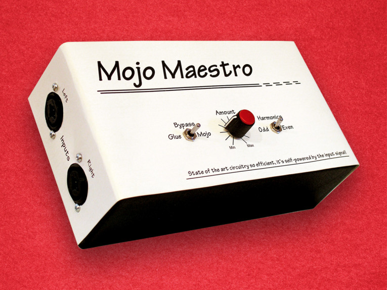
The Mojo Maestro is a simple box that can add distortion ranging from very subtle—to add a little grit to a sterile sounding instrument track or to help “glue” a full mix together—through severe clipping to add “mojo” or “dirt” to any musical source that will benefit. The Mojo setting also switches in a capacitor to gently roll off the highest frequencies to counter the added buzziness. With gentler settings, the overall effect is similar to running music through a tube amplifier or an analog tape recorder but without the added tape hiss and flutter.
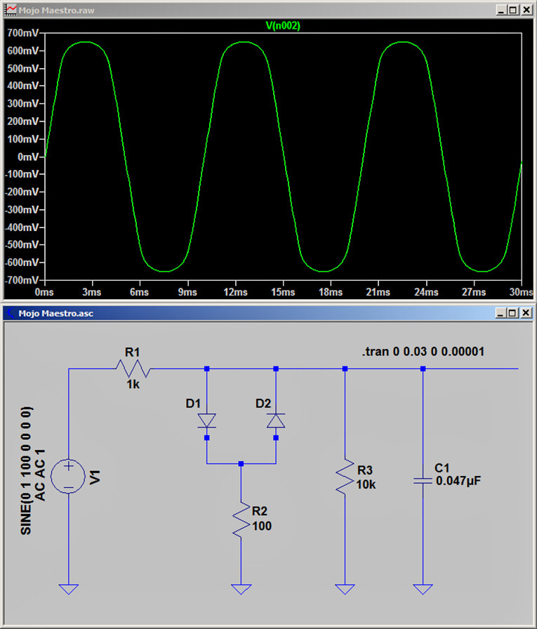
To devise this circuit, I used the free LTspice simulation software shown in Figure 1. Even though there are only half a dozen parts, this was an easier and faster way to choose appropriate resistor values than messing around with a physical breadboard and clipleads. LTspice lets you draw the schematic of an analog circuit and test it in software to see its frequency response and other attributes. Just as DAW software virtualizes an entire recording studio with effects plugins and even synthesizers, LTspice virtualizes a parts bin fully stocked with components, plus a workbench full of high-quality test gear.
In the past, I’ve used LTspice to verify the design of four-pole high-pass and low-pass filters, a multi-tone sawtooth wave generator-based on 555 timer chips, and a circuit that puts an audio isolation transformer in the feedback loop of an op-amp to minimize the transformer’s distortion. Compared to those, this circuit was child’s play! But the simulation was still very useful.
The oscilloscope view in LTspice lets me see how the waveform clips with different control settings and input voltages, and its Fast Fourier Transform (FFT) display shows exactly how much distortion is added at various frequencies. I settled on a 10 kΩ linear pot (replacing R2 shown in Figure 1) to vary the distortion from gentle to extreme, though I also added a switch with “Mojo/Glue” positions to control the maximum distortion amount.
Getting Your Mojo On
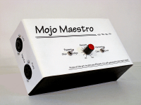
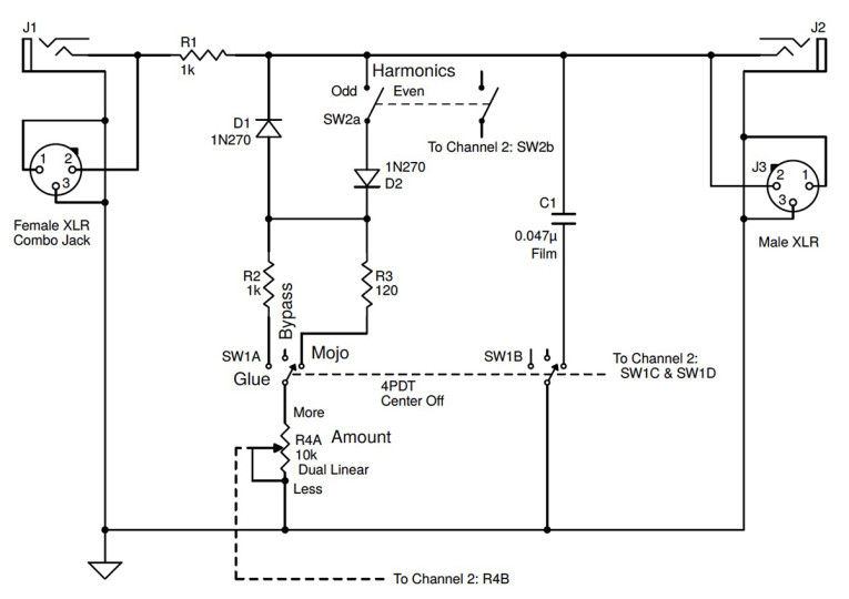
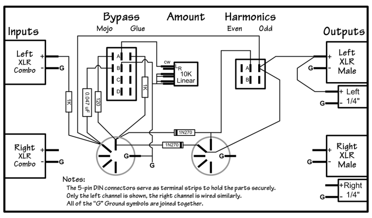
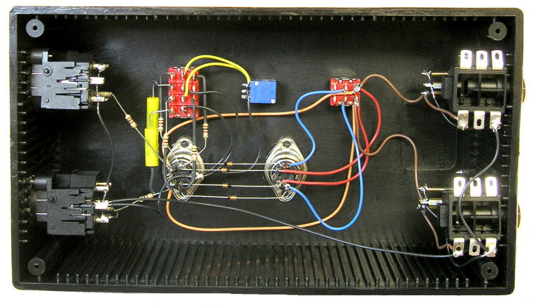
Figure 2 shows the schematic. Photo 1 shows the labeled plastic project case and Photo 2 shows the internal component assembly. Note that the 10 kΩ resistor in the LTspice schematic is present just to emulate the expected input impedance of the following device. The “real” schematic shown in Figure 2 details the parts I actually used. Since this is a passive device, its behavior depends on the input signal levels. Further, as you increase the distortion, the output level is reduced, so you may need to raise the volume later in the chain.
I initially built this device using 1N4148 silicon signal diodes that start to conduct around 0.6 V in their favored direction. That seemed like a good match for professional audio gear that operates at a nominal +4 dBu signal level (1.23 V). But I quickly realized that fairly large signals were required to get much of an audible effect, so I substituted 1N270 germanium diodes that conduct at around 0.2 V. This enables you to vary the effect amount from subtle to severe, using signal levels more typical of consumer devices while still accommodating professional gear operating at lower levels.
Mostly as a joke, but partly to hide that this is just a few passive components, I labeled the front panel “State-of-the-art
circuitry so efficient, it’s self-powered by the input signal!” Which, of course, it is.
I used a 4PDT toggle switch with a center-off position to allow a true bypass mode. Even with the Amount knob at minimum, there’s still some effect unless the input signal level is very low. The Odd/Even switch allows clipping only negative peaks to add both odd- and even-order harmonics, or it enables a second diode to clip both peaks which adds mainly odd harmonics. When set for “Glue,” the Amount control varies the soft clipping effect over a 10-to-1 range as limited by the 1 kΩ resistor R2.
The Mojo setting instead uses a smaller (120 Ω) limiting resistor to allow more aggressive clipping. This setting also engages C1 to gently roll off the highest frequencies, though you could leave out that feature and use a DPDT switch for SW1, which costs less and is more common. Or, you could experiment with other capacitor values to change the amount and the frequency range of the high-frequency reduction.
It’s worth mentioning that for static waveforms, symmetrical wave shapes contain only odd-numbered harmonics, and asymmetrical shapes contain both odd and even harmonics. So square waves and triangle waves contain only odd harmonics, where sawtooth and pulse waves contain both types. Also note that regardless of the Odd/Even Harmonics switch setting, intermodulation distortion (IMD) is always added along with harmonic distortion unless the input source is a single frequency. This is true for all electronic devices, including gear with tubes and transformers, and analog tape recorders. Also, every device that adds even-numbered harmonics also adds odd harmonics.
Further, when playing music, any type of harmonic distortion always adds a similar amount of IMD. I didn’t bother to test Mojo Maestro with multiple frequencies in order to measure the intermodulation components because measurements don’t really matter when the goal is adding color to a recording. But I did test the basic operation using a 100 Hz sine wave and included some screenshots.
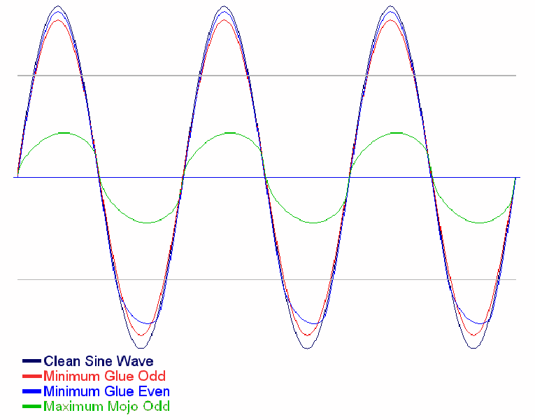
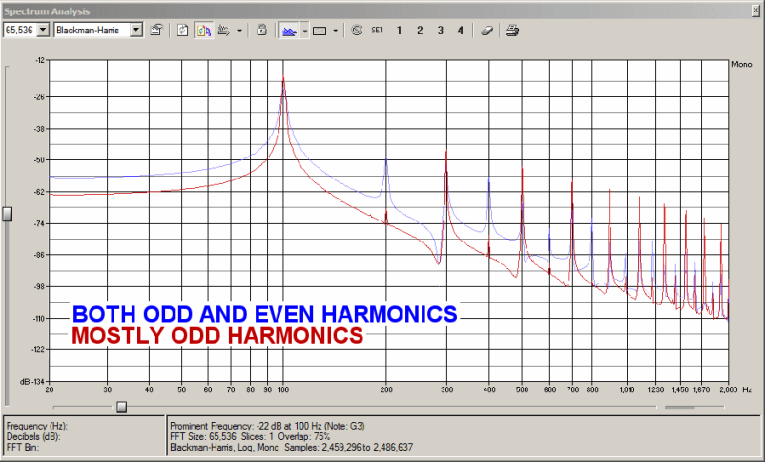
Figure 3 shows some of the waves I recorded through the unit using a few different settings. Figure 4 shows the FFT display with the generated odd vs. even components, when applying a fairly extreme amount of distortion. You can see that the red spikes are most prominent at 100 Hz and it’s odd-number multiples 300 Hz, 500 Hz, 700 Hz, and so forth. The blue spikes show the spectrum when only one diode was in the circuit, and that trace has spikes at every 100 Hz multiple of the 100 Hz fundamental.
Design and Assembly
To accommodate different devices, I used Neutrik’s clever NCJ6FI-S combination XLR and 0.25” connector for the left and right inputs, though separate connectors wired in parallel were needed for the outputs. I could have also added parallel RCA jacks for more flexibility, but I have so many adapters laying around that it wasn’t worth the effort. Of course, you can use whatever connector type(s) you prefer.
The schematic shown in Figure 1 only depicts the left channel, but the right channel is identical. Even though this device is useful in professional recording studios, it’s so simple it seemed silly to over-design it. So the XLR input and output pins 1 (ground) and 3 (signal negative) are tied together, then wired in parallel with the 0.25” jacks. The XLR pin numbers are obvious, and for the 0.25” phone jacks the terminal labels are Ring (unused), Tip (hot), and Sleeve (ground).
This circuit is too simple to require a PCB, but I still needed a way to securely mount the parts. I had a bunch of extra MIDI-style DIN jacks from another project, so I used Epoxy to attach two of them inside the case to use as stand-offs to hold the parts, similar to terminal strips. Even though I built Mojo Maestro into an unshielded plastic box, it’s meant to work with line level signals so I wasn’t worried about picking up hum or noise. Just as important, the circuit impedance is relatively low, which also minimizes hum pickup.
Almost every modern audio device has a low output impedance and relatively high input impedance, so it wasn’t necessary to use shielded wiring inside. To avoid wiring errors, I first made the layout drawing shown in Figure 5. Then, I soldered together all the parts and wires from that drawing rather than from the schematic.
I have a large collection of electronic parts that I’ve accumulated over time, and some are more than 40 years old. So I figured it would be prudent to at least check the diodes to be sure they’re still okay. I’m glad I did because one of them was marked backward. I checked it three times comparing it to four other diodes because in all my years I’ve never seen that!
I bought new switches and connectors for this project, so I didn’t have to worry about tarnish or corrosion on either the solder lugs or the internal contacts. Though I scraped off a bit of oxidization onto the diode leads to be sure they’d take solder well. Speaking of switches, when wiring toggle switches you’ll note that the terminals are opposite the handle position. Fortunately, if you wire it backward, you can simply rotate the switch 180° rather than have to unsolder then re-solder all the wires again. Likewise, always look carefully at a connector’s pin numbers because, when soldering at the rear, they’re reversed from the front view that’s usually shown in a datasheet!
The last audio device I built was much more sophisticated than this one, and was a big investment in both time and parts cost, so I didn’t mind spending $200 for a professionally punched and labeled front panel. I couldn’t justify that sort of expense for this simple project. So, I decided to print my own control panel onto card stock and glue that to the plastic project box. I used Microsoft Visio to design the connector layout, front panel holes, and labeling. Then, I printed it onto a piece of legal size paper. Next, I wrapped the paper around the box, and spot-glued the corners with rubber cement to hold it in place while drilling the holes.
A small “x” printed in the middle of each switch and connector hole made it easy to find the exact center when drilling. After all the holes were drilled and de-burred, I printed the panel once more, this time onto heavy card stock. After using an X-ACTO knife to make all the holes in the card stock, I glued it to the case using a thin coat of contact cement. Finally, I mounted the connectors and other parts. Card stock isn’t as durable as real engraving or silk screening, but it looks a lot nicer than Dymo plastic labels! You could use colored card stock if you prefer, or spray it with a coat of lacquer after printing for protection against wear and smudges.
Listen for Yourself
To hear the results of the Mojo Maestro, go to the Supplementary Material section of the audioXpress website and download the Zip file. In the file, you will find six audio examples, made using different settings of either Glue or Mojo, Odd or Even, and the Amount knob position.
Modifications
Besides trying different capacitor values to tame some of the brightness when adding more severe distortion as mentioned, you might want to try adding a pair of real audio transformers because that colors audio differently than clipping. The Triad TY-250P has reasonable fidelity at normal line levels, and at less than $6, it’s very affordable. This transformer claims a response that’s flat within 1 dB from 20 to 20 kHz, and it can handle up to 20 mW, which is adequate for line level devices even at the higher levels professional audio devices often have to handle.
If you try this, I suggest you connect the transformer at the circuit’s input to control how much signal is applied to the transformer before clipping kicks in. Otherwise, the diodes would limit the level and restrict how hard you can drive the transformer into saturation. ax
Parts List
Two of each, for the left and right channels:
R1: 1K
R2: 1K
R3: 120
C1: 0.047 uF film
D1 & D2: 1N270 or equivalent germanium diodes
Input and output connectors that match your audio equipment
One each:
R4: 10K dual linear potentiometer
SW1: 4PDT toggle switch, center off
SW2: DPST toggle switch
Plastic or metal case large enough to hold the parts and connectors

About the Author
Ethan Winer has been an audio engineer and professional musician for more than 45 years. He’s currently a principal at RealTraps where he designs acoustic treatment products for recording studios and listening rooms. Ethan’s “Cello Rondo” music video has received nearly two million views on YouTube and other websites, and his book The Audio Expert published by Focal Press is available at amazon.com and his own website, ethanwiner.com.
Audio Files
To download the audio files, visit our Supplementary Material page.
Source
LTspice, Linear Technology | www.linear.com/designtools/software/#LTspice
This article was originally published in audioXpress, October 2017