Reamplification is an increasingly common procedure for audio production. Often, when an ensemble is recorded to a multitrack master that is intended for later mixdown, it is desirable to put off some of the decisions about sound until the mixdown session.
This option has become very popular in recent years, as we have had increasing numbers of tracks available in the modern digital production studio and wanted more options available for mixdown. However, the practice also has several other applications. For example, a well-known guitar player has a reputation for constantly turning up his amplifier over the course of the evening, starting out with it much too soft and ending up with it much too loud.
With guitar amplifiers being what they are, not just the volume changes, the instrument’s tone changes as well. For live recording, the sound crew records a DI feed off his instrument, then later reamps it in the studio. This means all the tracks recorded that evening will have the same basic tone.
To reamplify, you need a box that takes the balanced output from your console or recorder and turns it into a high-Z unbalanced output that matches a typical instrument’s impedance. Then, it can go into an amplifier. Since there is some interaction between the pickup and the amplifier input stage, it can also be worthwhile to have a device that models the source impedance of a typical pickup. And, of course, it’s important to be able to isolate the instrument amplifier’s ground from the rest of the studio grounding system.
How It Works
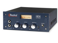
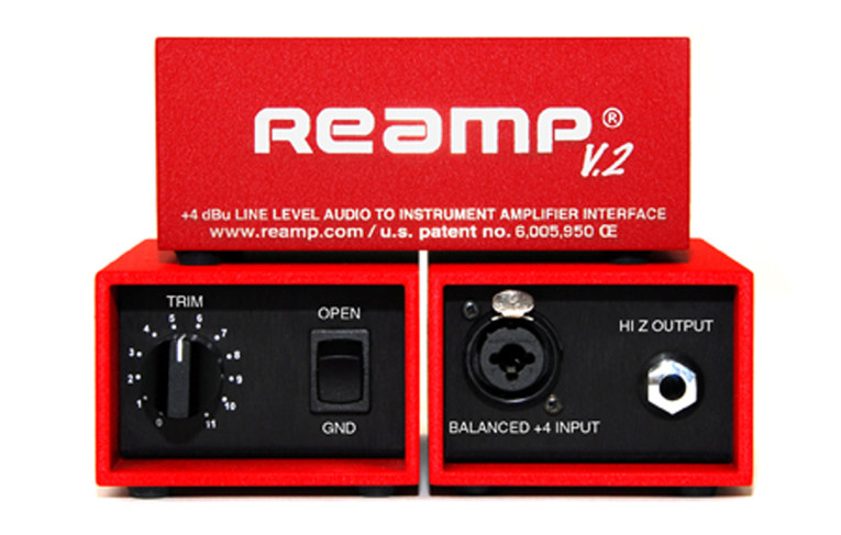
John Cuniberti patented one excellent way of doing this and it was sold commercially under the product name “Reamp” (see Photo 1). In an interview with Recording magazine years ago, Cuniberti talked about how using a conventional DI box wired in reverse for reamplification was unsatisfactory and resulted in poor low-frequency response (which I have also found to be the case).
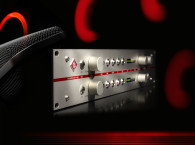
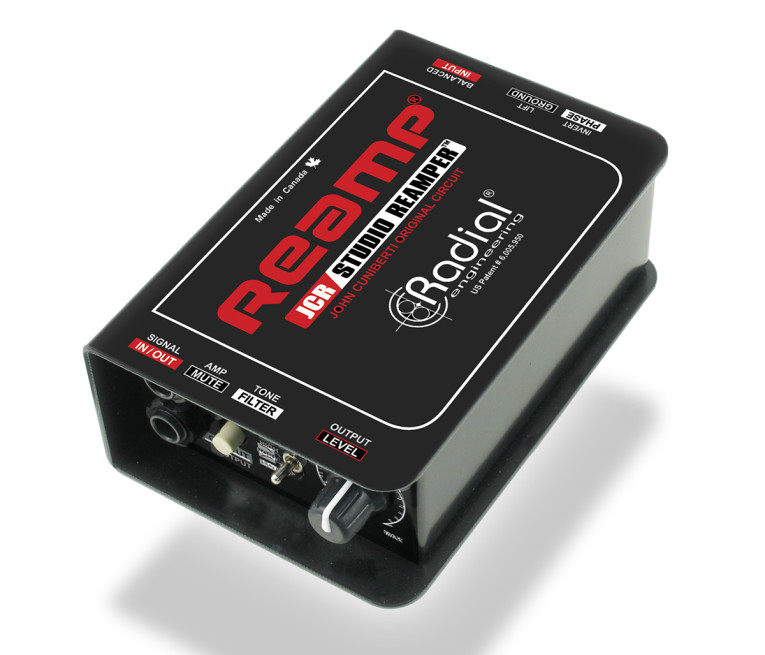
Cuniberti’s patent, US Patent 6005950, details the use of the special transformer design and it is well worth reading because it provides a very ingenious approach to the problem. In 2010, Radial Engineering purchased the Reamp patent, trademark, and all business assets from Cuniberti (see Photo 2). However, the Reamp requires a special transformer. And while it does an excellent job, it only enables one sort of pickup to be modeled.
The Kludge
So, we’re going to take a totally different approach because building something on the bench with off-the-shelf parts makes it impossible to use special purpose transformers. Instead, we’re going to make my Kludge reamp box using lumped-sum elements to simulate the source impedance of the pickups. This works well, doesn’t infringe on the patent, and is very similar in actual practice.
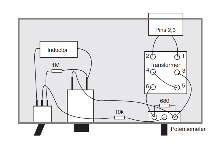
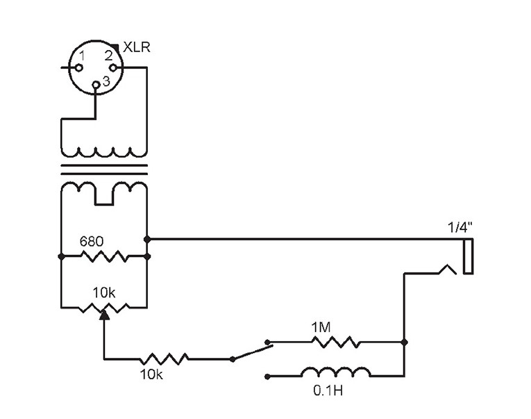
This project uses an inexpensive 600:600-Ω transformer because it is easy to cheaply manufacture a good low-ratio transformer. The transformer’s output goes into a 680-Ω load resistor, which absorbs most of the signal going into it. It also ensures the transformer is as neutral as possible because it’s properly loaded (see Figure 1). One of the unfortunate issues with the inexpensive transformer is that it is very touchy about loading.
A tiny amount of signal is tapped off, run through a volume control, and then into some resistors and inductors that simulate pickup source impedances. Since the transformer is expected to be neutral and not to be part of the load simulation, we get around much of the high-cost componentry of earlier designs at the minor expense of signal level. Even so, there is plenty of level available going into almost any amplifier.
The impedance switch enables you to select between a purely resistive (1-M) source, or an inductive one (10 kΩ plus 0.1 H). These are somewhat simplified models, and the inductance of many pickups is much higher than that, but they both provide good sounds that are roughly representative of some pickups.
Now, when my original article came out, some people pointed out that pickups widely vary and there are literally hundreds from which to choose, each presenting somewhat different source impedances. I selected two reasonable types that are very different from one another and typical of what you’d find with standard studio instruments.
You can also add a rotary switch to select dozens of different resistor, inductor, and capacitor (RLC) combinations. However, in a decade of using this device, I have found these two pickup models do just about everything I want. But, if you are not completely happy with them, feel free to use some equalization on the feed.
Building It
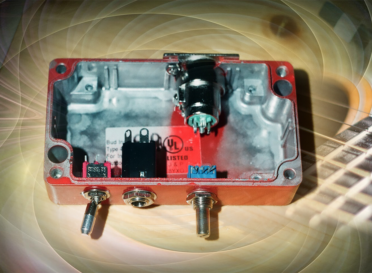
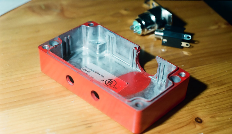
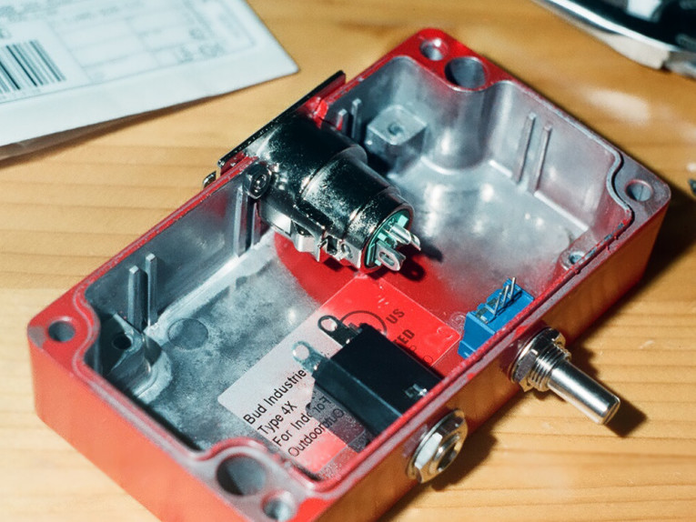
The hardest part of building this box is the actual metalworking. The box is solid die-cast aluminum (see Photo 3). The hole for the XLR jack is an 0.6875” hole, and I have always made these by drilling out with a 0.75” hole saw. (The ones sold for use with wood also work with aluminum, if you keep them well-lubricated with cutting oil as you use them.) Then, I filed the hole out with chainsaw files to size.
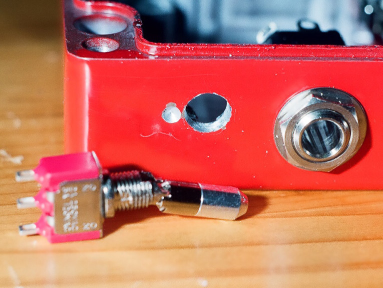
I made a 0.25” hole for the switch and two 0.375” holes for the potentiometer and the phone jack, but they might need to be filed out a little bit (see Photo 4). The switch also requires a small hole to be drilled in the case to lock the front notched washer into place (see Photo 5).
The switch is one that locks into place. You need to pull out on the toggle to move it. I find this a huge advantage for DI boxes and other gadgets used in stage environments and just decided to use the same switch here. If you substitute for another type of switch, be sure that it’s one with gold-plated contacts. Because the levels involved here are so small, switches with conventional contacts will tend to become unreliable after a couple years.
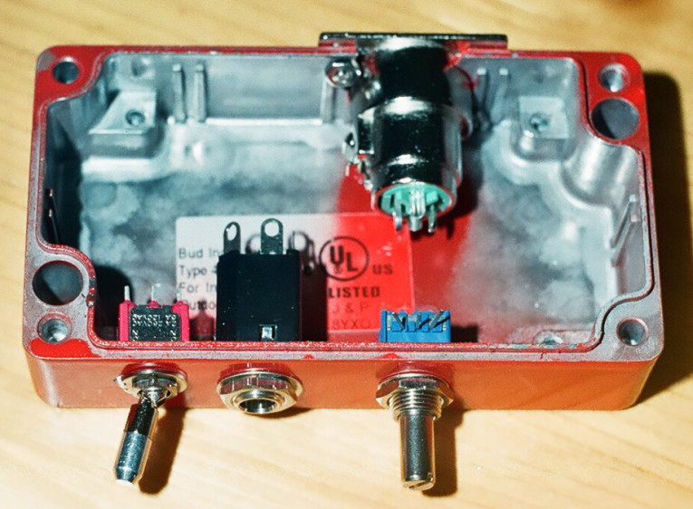
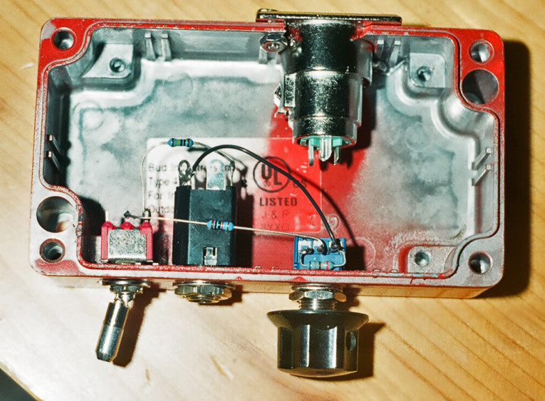
Prior to starting the assembly, refer to Figure 2. Photo 6 and Photo 7 demonstrate how the Kludge reamplifier box should look once the build is completed. Be sure to cement the top of the transformer upside-down to the case so that it doesn’t move around. A little epoxy or silicone will keep it in place. Since you’re not actually using it on the wiring, you don’t need to worry about special adhesives.
Using the provided parts list, the Kludge reamplifier can be built for less than $60. I also think you’ll like the way the unit sounds. The two different switch positions provide very different tonal characteristics, which I have found useful for the guitar and the bass.
| Quantity | Part | Digi-Key Part Number |
|---|---|---|
| 1 | Female panel XLR | SC1009-ND |
| 1 | 10-kΩ audio taper potentiometer | 51AAD-B28-D15L-ND |
| 1 | box | 377-1101-ND |
| 1 | jack | SC1316-ND |
| 1 | Tamura transformer | MT4152-ND |
| 1 | 0.-H inductor | M8393-ND |
| 1 | SPDT locking switch | CKN1215-ND |
| 1 | knob | 226-4033-ND |
| 1 | 681-Ω resistor | 681XBK-ND |
| 1 | 1-M resistor | 1.00MXBK-ND |
| 1 | 1-kΩ resistor | 10.0KXBK-ND |
Author’s Note: Some of these Digi-Key part numbers are different than those in my original online article, mostly because of manufacturer’s changes to Restriction of Hazardous Substances (RoHS) materials.
This article was published in audioXpress, January 2015.
Resources
J. Cuniberti, “Recorder to Instrument Amplifier Interface Apparatus and Method,”
www.google.com/patents/US6005950.
Digi-Key Corp. - www.digi-key.com
S. Dorsey, “Build Your Own Reamp Box,” Recording magazine www.recordingmag.com/resources/resourceDetail/314.html.