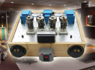
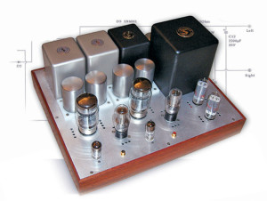
I’ve been on a quest for the ideal tube power amplifier. Aren’t we all? To me, the ideal amplifier is simple, powerful, and sounds good simple goals. Unfortunately, these goals are all at odds in the real world. But I’ve come up with a design that I think hits the mark pretty well (Photo 1).
Power Amp Topologies
There are several different basic topologies used to build tube power amplifiers. You can group them into two basic divisions: push-pull and single-ended; with numerous variations within each group, such as ultra-linear connection, parallel feed, and so on, and you can use different devices (triodes, pentodes, and so on). There are devoted followers of all types who believe theirs is the best, often with great conviction!
Push-pull amplifiers, by their nature, cancel a good amount of the distortion that’s inherent in a tube amplifier. They can also deliver more power than single-ended amplifiers, if they are biased such that one of the tubes is cut off on part of the signal swing (class-AB operation). But push-pull amps are more complex than single-ended amps, requiring a phase splitter, and twice as many output tubes. And the distortion cancellation is only of even-order harmonics, as I’ll discuss shortly.
Single-ended amps are simpler, requiring fewer active stages. They do not benefit from the distortion cancellation of opposing tubes as a push-pull amplifier does, so they typically have high distortion. For example, 1% THD at 1W is not uncommon for a typical SE triode design.
FFTs and The Sound Of Harmonic Distortion
Without getting too technical, you can transform a representation of an electrical signal from the time domain into the frequency domain by doing a “Fourier transform.” Think of a waveform on an oscilloscope, with time on the horizontal axis and amplitude on the vertical, as opposed to the display on a spectrum analyzer, with frequency on the horizontal axis. A pure sine wave would be represented by a single peak on a spectrum analyzer display, at the frequency of the sine wave.
If you distort that sine wave, peaks start to appear at other frequencies the sine wave is no longer “pure.” Nonlinearities in an amplifier will cause energy to appear at the harmonics of an input sine wave’s frequency. This is called harmonic distortion.
As an example, if you apply a 1kHz sine-wave signal to the input of an amplifier, you will get at the output mostly an amplified 1kHz sine-wave signal, a reproduction of the input. But you will also get small amounts of energy at 2kHz, 3kHz, 4kHz, and so on. These are harmonic distortion products, the 2nd, 3rd, 4th, and so on, harmonics of the 1kHz inputs signal. The amount of each of the harmonics, or “harmonic profile,” is key to our perception of how an amplifier “sounds.”
Different types of distortion result in different mixtures of harmonics. The spectrum of a square wave, for instance, contains the fundamental frequency and all odd harmonics, but no even harmonics. You can see how an amplifier heavily into symmetric clipping, then, will generate many odd harmonics.
You can see the other extreme on a single-ended tube amplifier stage, that is biased very close to plate current cutoff; it generates a lot of even - but not much odd - harmonic distortion.
Though it's a bit of oversimplification, you can think of odd-order distortion as symmetrical; i.e., acting on both the upper and lower parts of a waveform. Even-order distortion, on the other hand, is asymmetrical, acting only on the lower or upper part of the waveform.
There have been many articles on the psychoacoustics of harmonic distortion, both old and new, so I won't dwell on it too much here. Some may disagree, but I believe the following to be true:
- less distortion is better than more distortion
- even-order distortion (2nd, 4th, and so on) is less audible than odd-order distortion (3rd, 5th, and so on)
- low-order distortion (2nd, 3rd, and so on) is less audible than high-order distortion (5th, 6th, and so on)
- low-order distortion tends to mask higher-order distortion
I think most people would agree that the ideal amplifier would have no distortion. You can' achieve that, so the next best thing is to minimize distortion, but keep the distortion profile such that low, even-order harmonics dominate, and don't allow large amounts of high-order odd harmonics.
Single-Ended vs Push-Pull
As I mentioned previously, push-pull (P-P) amplifier, by their nature, cancel a large percentage of even-order harmonics. They do this because of their symmetry. The opposing tubes, each having similar nonlinearities but operating in opposite polarity, tend to behave together as a more linear amplifier.
If you look at the distortion spectra of push-pull amps compared to single-ended amps, they are typically very different. SE amps have lots of 2nd harmonic, and P-P amps have very little, since much of it gets cancelled. The harmonic profile of many P-P amps is dominated by the 3rd harmonic. This is the primary sonic difference between P-P amps and SE amps, and somewhat explains the debate about which sounds better. P-P amps usually have less overall distortion, but the distortion tends to be more odd-order.
To me, neither high-distortion SE nor P-P amps sound great. They are different, to be sure. I can listen to a high-distortion SE amp with some types of music and it sounds quite nice, but with complex music, the sound becomes muddy. In fact, I had convinced myself that 1-2% of 2nd harmonic actually sounded better than a lower distortion amplifier, until I listened to a wider variety of music. High-distortion P-P amps generally sound harsh and annoying to me, especially with simple music.
On the other hand, low-distortion SE or P-P amps can both sound quite good to me. So I’m a firm believer that the topology doesn’t matter. It’s the quantity, and nature of, the distortion generated that’s important. From a design standpoint, I favor an SE amp, mostly because of its simplicity, and the fact that by their nature SE amps tend to generate more even than odd-order distortion. The design problem, then, is how to achieve acceptably low distortion with a simple SE amplifier design.
The E-Linear Amp Design
You can approach the problem of keeping distortion low and power output high from a number of directions. One of the main approaches is to add feedback into the amplifier to correct nonlinearities. You can apply feedback from output back to the input. This is called global, overall, or loop feedback. I’m not a big fan of this type. It can be difficult to stabilize such circuits, which tend to introduce some higher-order distortion products. I haven’t listened to many amps with loop feedback that sound good.
You can also apply feedback locally to a single amplifying stage. An un-bypassed cathode resistor is a simple implementation of local feedback. It lowers the gain and distortion by feeding back part of the output signal to the input and moving the cathode voltage in response to the plate current.
The ultralinear connection, popularized by the hi-fi push-pull amps of the ′60s, is also a form of local feedback, in which part of the output signal (typically around 40%) is taken from a tap on the output transformer and fed to the screen grid.
The E-linear amplifier starts with an ultralinear-connected output stage and adds another local feedback path from the output transformer (and screen grid) to the control grid of the output tube. This combination of multiple local feedback paths dramatically lowers the distortion and output impedance of the output stage and gives you performance that cannot be obtained with pentode, triode, or ultralinear connection alone. It sounds good, too!
Feedback from plate to grid is certainly nothing new. An article published in 1938 by an RCA engineer describes in detail the use of plate-grid feedback to tailor the characteristics of a beam power tube for audio amplifier use. The ultralinear connection has been around since the early 1950s an invention usually credited to David Hafler. The E-linear configuration can be viewed somewhat as a combination of the two.
The term “E-linear” was coined recently by Emotive Audio (www.emotiveaudio.com) as a description for the combination of ultralinear feedback to the screen grid of the output tube and to the driver stage, or to the control grid of the output tube. I’d be surprised if nobody had tried this earlier, but I haven’t found any references to this type of output stage connection. It seems that several people started playing with this configuration at about the same time, including myself.

Design Details
I wanted this amplifier to have only two stages and to generate at least 10W of output power. To accomplish this, as well as have enough gain to be able to apply the E-linear feedback scheme, high transconductance (Gm) pentodes (or beam tetrodes) are almost a must. I tried many different tubes, both driver and output types. To get the output power and low distortion that I wanted, I wound up using a KT88 beam power tube as the output tube and a D3a pentode as the driver.
The D3a (also known as the 7721) is a German tube used in telephone equipment, made by Telefunken, Valvo, and Siemens. The D3a is uncommon in North America, so I know many of you will ask, “Isn’t there another tube that’s easier to find that will work?” My answer is that although there are other tubes that will work, I don’t know of any that will work nearly as well. I tested many pentodes (for details, see my web page at www.pmillett.com/pentodes.htm). The D3a performed the best by far in this particular circuit.
I can’t say with certainty exactly why the D3a worked the best in this circuit. There are certainly other driver pentodes that have higher Gm and lower distortion than the D3a when measured alone. But in combination with the KT88 output stage, the D3a was the clear winner. This may be partly due to distortion cancellation between the D3a and KT88 two SE amp stages can partially cancel even-order harmonics in much the same way that a P-P amp does. Perhaps the D3a is just a very good match for the KT88. D3a tubes are easy to find and are fairly inexpensive in Europe. These days, it’s as easy as getting on the Internet or the telephone (don’t forget the time difference though!) and placing an order with a credit card. In a few days your tubes will arrive in the mail, direct from Europe. Some suppliers who sell D3a tubes are listed at the end of this article.
The screen grid of the D3a driver stage is supplied with a shunt-regulated 150V supply. Regulation is provided by a 0D3/VR150 gas discharge VR tube, one for each channel. The plate of the driver is capacitively coupled to the KT88 control grid using a good-quality coupling capacitor. I’ve never been really excited about using designer audiophile capacitors, but this time I decided to see what I was missing. I used Auricap film capacitors, which have received very good reviews, are reasonably priced, and appear to be very well built.
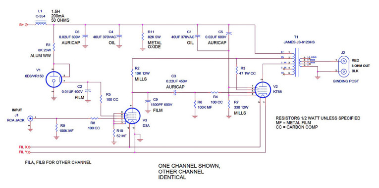
The resistive plate load for the D3a is connected to the screen grid of the KT88, and both are connected to a ~40% ultralinear tap on the output transformer, which provides the E-linear feedback. Refer to Fig. 1, the amplifier schematic, for details.
Since a pentode has very high plate resistance, the driver’s output impedance is dominated by the plate load resistance, which needs to be low enough to provide plenty of drive to the KT88 control grid. It also allows the feedback from the ultralinear tap to be coupled directly to the KT88 control grid. A pentode almost acts like a constant-current source, so any AC voltage you apply to the top of the load resistor will appear on the plate virtually unchanged.
If you used a triode driver, the triode’s relatively low plate resistance would form a voltage divider with the plate load resistor and decrease the amount of feedback. The E-linear scheme still works in this situation, but the amount of feedback effectively getting coupled to the output tube grid is reduced by approximately a factor of Rp/(Rp+Rl), where Rl is the plate load resistor and Rp is the driver tube’s plate resistance.
You will notice a small (1500pF, or 0.0015μF) capacitor from the D3a plate to ground. This capacitor provides a drop in gain at very high frequencies and is advisable because any inductance in the driver’s plate circuitsuch as a wirewound plate load resistor, or even the inductance of the wiring results in increasing gain at high frequencies.
This gain, in combination with phase shifts in the output transformer, can result in RF oscillation. I selected this capacitor, which mitigates the gain increase to prevent oscillation, based on tailoring the frequency response and by minimizing any ringing on squarewave signals.
Along those same lines, I used grid-stopper resistors on all the grids. These resistors, which should be carbon composition for minimum inductance, help eliminate RF tuned circuits from being parasitically formed with the wiring of the grid circuits, which can also lead to high-frequency oscillation in high-Gm tubes.
To achieve the lowest distortion and output impedance, run both the D3a driver and KT88 output tube close to their dissipation limits. I can’t tell you how this will affect tube life, but since the D3a is a long-life telecommunications tube, I expect it will still last quite a while. I don’t have much experience with the different KT88 tubes, but I know many amplifier designs using KT88s run at or over the limits successfully.
The KT88 is biased with a cathode resistor. You’ll notice that there is no cathode bypass capacitor or actually, that the cathode is bypassed to the B+ side of the output transformer. This “ultrapath” capacitor provides the AC current return for the output stage, so most of the current flows in a loop through this capacitor, the OPT, and the KT88. The theory here is that you need to keep as much of the signal current out of the power supply as you can.
If you can live with lower output power, you can also use this same circuit with any number of pentodes or beam tetrodes. I tried the 12E1, 6L6, EL34, 807, and a few others, singly and in parallel, and all worked well. The 12E1 performed almost as well as the KT88. Just change the cathode bias resistor to get the operating current low enough so the plate dissipation is just under the rated limit and select the output impedance tap appropriate for the tube.
Output Transformers
Probably the single most critical component in a SE amplifier is the output transformer. I’ve tried quite a few, including some expensive Japanese transformers I picked up while traveling.
I heard through the Internet of an inexpensive brand of transformers made in Taiwan, called James. James iron was (at the time) unavailable in the US, but was quite popular among the East Asian (Hong Kong and Taiwan) DIY crowd. Well, hard-to-get parts hadn’t stopped me before! I bought a pair of SE output transformers, James JS-6123HS, on eBay to see whether they were as good as what I’d heard. They were indeed quite good, measuring just as the specs indicated, and looking every bit as good as the Tango XE-20S, a much more expensive transformer available in Japan.
Like the XE-20S, the JS-6123HS is a “universal” SE output transformer, with taps for 2.5k, 3.5k, and 5kΩ primary connections, as well as an ultra-linear (screen grid) tap. It also has 4, 8, and 16Ω taps on the secondary, which makes for a versatile transformer, great for experimenting. This transformer became the basis for many breadboard experiments, one of which resulted in the amplifier described here.
The fact that James transformers weren’t available in the US actually delayed my writing this article for a time. I figured most readers wouldn’t be very happy having to pay to ship 50 lb of iron from Taiwan (air shipping costs almost as much as the transformers). I also wasn’t sure how well other transformers would work in this design, since it is a little unconventional. It’s possible that some transformers would have enough phase shift at high frequencies that they may not be stable with the E-linear feedback configuration. I think James transformers have the best cost/performance of all the audio transformers I’ve used.
Power Supply
I built a stereo amplifier, and for a simple two-stage amp, this design’s power requirements are substantial. I used a B+ voltage of 425V, with a total current requirement of about 360mA. This breaks down to 100mA for the output stage, 40mA for the driver, and 30mA for the shunt regulator for the driver screen, per channel. The D3a driver draws significant screen current as it nears saturation, so lots of current needs to flow through the shunt regulator tubes to keep the screen voltage from dropping out on peaks.
A big power transformer is required for this amplifier, with a B+ winding of around 760V CT at 400mA DC. James has a wide range of power transformers, and luckily for North American builders, Taiwan has the same power supply (115V 60Hz) as the US. I used a JS-9618 mains transformer, which I lugged back from Taiwan in a suitcase. It’s a beast at almost 20 lb!
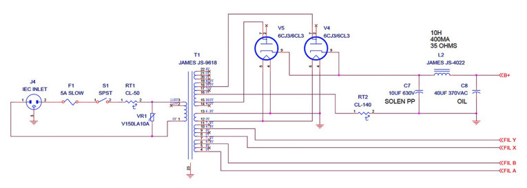
I used tube rectification and CLCLC filtering in the power supply. Refer to Fig. 2, the power supply schematic, for details. You need large rectifier tubes to deliver this much power supply current. I tried paralleled 5U4GB rectifiers, but the voltage drop across the rectifiers was quite large, making a “soft” HV supply. I also tried mercury vapor rectifiers, which worked well but required extra circuitry to provide a warm-up time, and caused a big start-up surge once I applied plate voltage.
I settled on color TV damper diode tubes (6CJ3, 6CL3, or equivalent) as rectifiers. They provide a low voltage drop (actually lower than the Mercury-vapor tubes), a nice, slow, controlled start-up, and simplicity. They’re also very inexpensive.
Filtering is provided by a CLC filter shared by both channels, followed by a second separate LC filter for each channel to provide some isolation. Sticking with the matching James iron, the first filter inductor is a 10H, 400mA JS-4022, which is the same size and shape as the output transformers. The second choke is a 1.5H, 200mA C-354 Dynaco replacement choke, a nice part available from Triode Electronics.
I used all polypropylene filter capacitors a small axial-leaded Solen cap in the first stage, and oil-filled motor run capacitors for the others. Polypropylene-in-oil motor run caps are quite a bargain. They are available new on eBay for only a few dollars each, or you can order them from distributors such as Allied Electronics for a bit more. A 370V AC rated capacitor is good for 600V DC (I confirmed this with the manufacturer). I also bypassed the motor run caps in the signal path with small Auricaps.
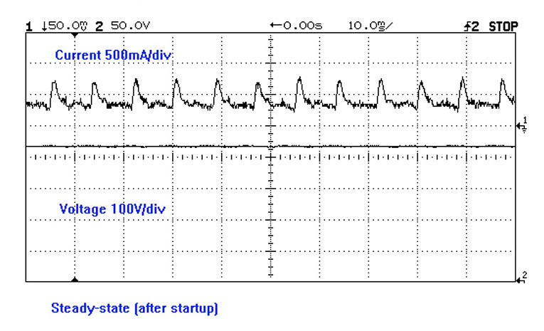
When designing power supplies with tube rectifiers, you must be careful not to exceed the peak-current capability of the rectifier tubes. Many designers use a capacitor that’s too large in the first stage of the filter, which causes the peak current through the rectifier to be very large, which in turn drastically shortens the rectifier’s life. Large current spikes also tend to couple noise everywhere. Just to be certain, I measured the repetitive peak current as shown in Fig. 3, which shows the peaks to be about 750mA. This is well within the ratings of the 6CJ3. I used an inrush current limiter between the transformer center tap and ground to limit the current surge at start-up. I suspect that this is unnecessary with the slow-starting damper diode rectifiers, but I left it in after experimenting with mercury-vapor tubes, where it was definitely needed.
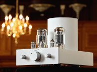
Implementation
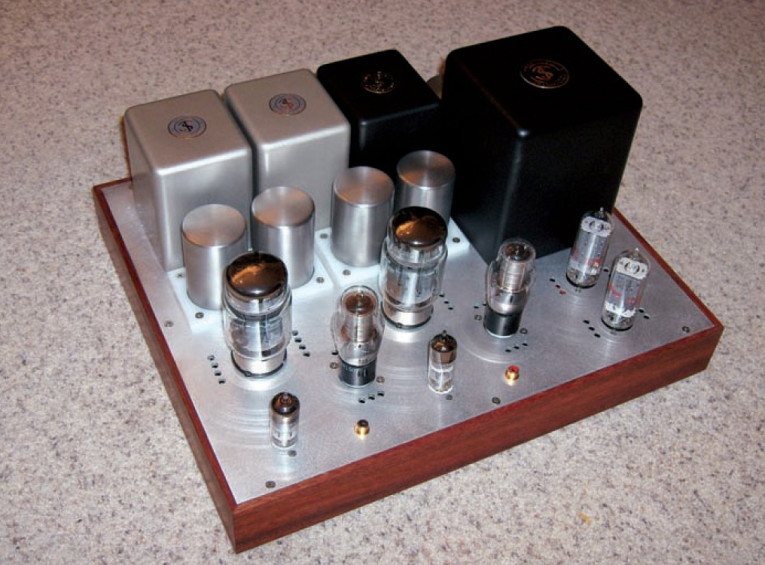
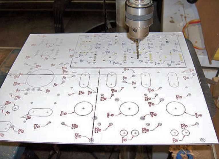
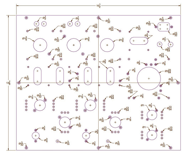
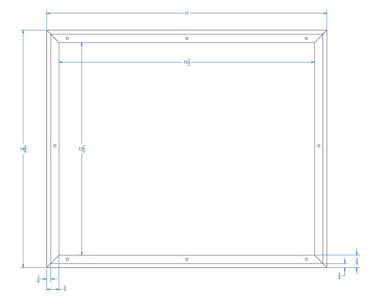
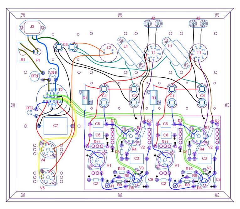
I built the amplifier on a metal chassis plate, mounted to a wooden base (Photo 2). I used a terminal board to mount most of the components inside. The amplifier measures about 17″ wide (which is about as large as I could fit into my stereo rack) and is just over 14″ deep. I fabricated the metal chassis plate, starting with a cut-to-size piece of 0.075″ thick 6061-T6 aluminum sheet I bought from Online Metals. I printed 1× scale drawings of the chassis plate (Fig. 4) on full-sheet sticky label stock, and applied them to the sheet. I find that this is an easy, accurate way to transfer a design to a piece of metal.
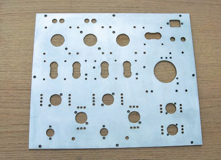
Just make sure you measure the prints so that your printer is really printing at the correct scale! I then cut the holes, using a drill press, step drill (Unibit), chassis punches, and a reciprocating saw. Photo 3 shows the panel on the drill press. I finished the aluminum simply by texturing the surface with a belt sander. The finished panel is shown in Photo 4.
Note that there are ventilation holes drilled opposite the power resistors, near the tubes. This provides a bit of airflow through the chassis. The amplifier still becomes quite warm during operation, because there is quite a bit of power being dissipated.
I built the amp using a terminal board to hold many of the components. I talked about this construction method extensively in an article that was published previously (A Low-Mu Triode Preamp - aX 2/04), so I won’t dwell on it here.
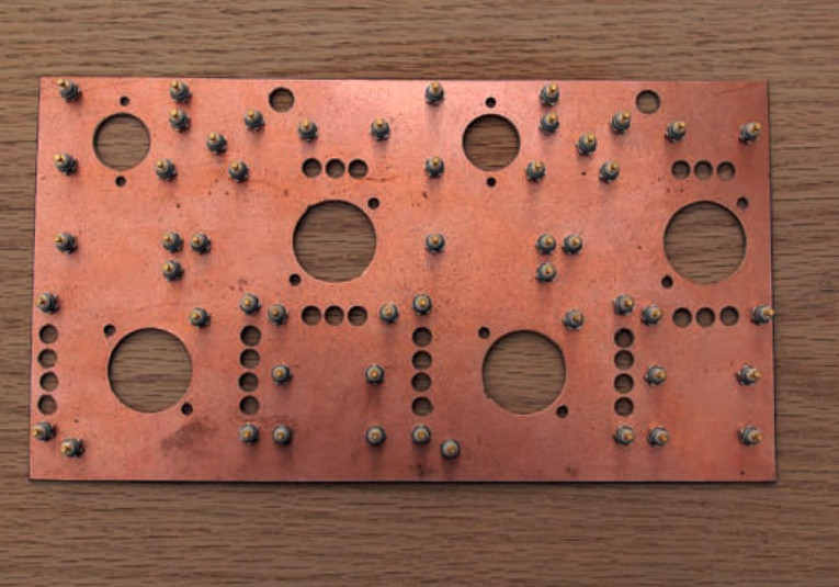
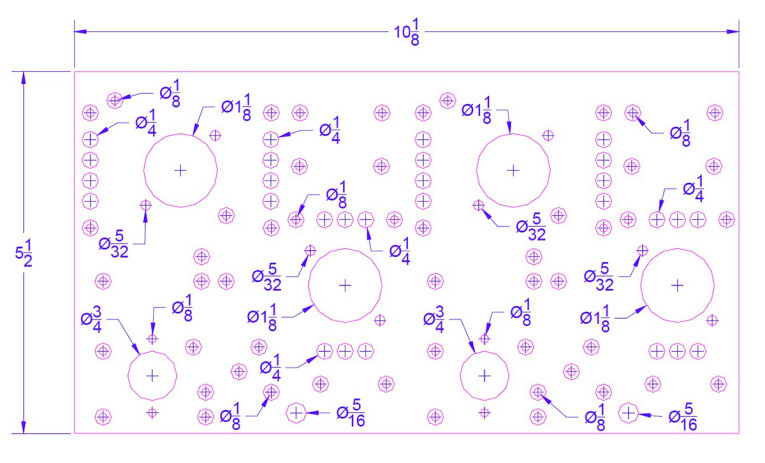
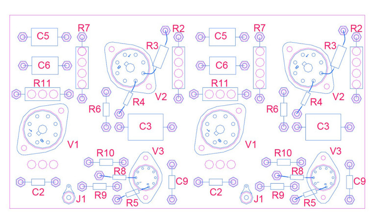
I used a piece of blank PCB material to mount single-point solder turret terminals, which are positioned exactly where you want to place components. I used the copper foil as a ground plane. Figure 5 shows the dimensions of terminal board, with parts placement in Fig. 5A; Photo 5 shows the complete (unwired) terminal board.
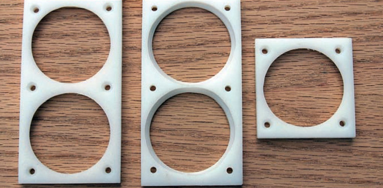
Mounting the oil-filled motor run capacitors presented a bit of a challenge. You can buy metal clamps to attach them to the chassis, but they’re large and not very nice looking. I made some clamps (Photo 6, Fig. 6) to hold the caps onto the chassis, using some plastic sheet that I had sitting around (you could also use wood or other material). Drill a hole through the sheet just big enough for the capacitor body to slip through, but not big enough for the rolled lip on the can to pass through (2″ worked just right for the caps I used).
Using a router, I cut a small rabbet into the plastic for the lip, so that the completed clamp sits flush on the chassis, capturing the lip on the can and holding it to the chassis. I slipped a thin rubber o-ring around the cap before passing it through the clamp to provide a firm grip on the cap, then secured the clamp to the chassis plate with screws.
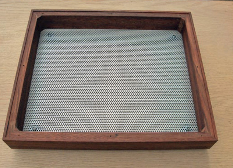
I made the wooden base in the same way as the one I made for the low-mu preamp using a perforated aluminum sheet from a local surplus store for the bottom to allow some ventilation. You can see the finished wooden base in Photo 7. Figure 7 shows the dimensions of the base.
To help you duplicate this design, you can download full-scale drawings as well as CAD source files (should you wish to make some changes) from my website at http://www.pmillett.com/elinear.htm. You can then use a printer to generate accurate templates to fabricate the parts. Parts are listed in an Excel sheet.
Wiring And Component Installation
I used the space underneath the large transformers and inductor to hide the screw heads for some of the components mounted on the underside of the chassis, such as the second stage filter chokes and some power components. I mounted these to the chassis plate first, using flush-head screws. I mounted the metal-cased wirewound resistors feeding the 0D3/VR150 shunt regulator tubes for the drivers to the chassis in this way as well, so that the chassis plate can act as a heatsink for them. A little thermal grease under the resistors is a good idea to improve the heat transfer.
I secured the terminal board to the chassis plate with the screws that mount the tube sockets. Then you can mount the remaining chassis parts (transformers, chokes, and so on) to the top of the chassis. I mounted the motor run caps to the chassis using the fabricated clamps.
With all the parts mounted to the chassis, install the wiring. I used Teflon hook-up wire, both solid and stranded. Solid wire, which is easiest to wrap around the terminals, is best to make a tightly twisted pair, such as I used for AC filament wiring. Refer to Fig. 8 for details of the wiring. Note that not all tube sockets are oriented with the same rotation as the ones I used, so you may need to make some adjustment.
The sockets I used were very nice Chinese ceramic ones from Angela Electronics. Hint: select the tube sockets you want to use before you start punching holes in the chassis, since they vary quite a bit in actual diameter. The sockets I bought turned out to be a little small for the holes I punched not enough to cause a problem, but they were a bit loose fitting.
After completing the wiring, I installed the leaded components on the terminal board and single-point terminals, wrapping their leads around the terminals and soldering. Adding the parts after the wiring makes it easier to change them after the fact, if you want to try different component values. A view of the inside of the completed chassis is shown in Photo 7.
Measurements
My goals included an output power of at least 10W, low output impedance, and low distortion. The measurements provide an indication of how well I met these goals.
At 5% THD (which is roughly the onset of clipping), the amplifier delivers 15W (per channel) into an 8Ω load. The output impedance on the 8Ω output tap measures about 2Ω, which gives a damping factor of 4, respectable enough for a SE amplifier. At 1W output, THD + noise is about 0.2% lower than most typical SE triode amplifiers. THD rises gradually to 1.8% at 10W out.
Noise at the amplifier output measured 0.5mV in the left channel and 1mV in the right, consisting of mostly 120Hz hum. I suspect the right-channel noise is higher than the left due to coupling between the filter choke and the right channel output transformer, because I didn't see this noise when the amp was in the breadboard stage and spread out a bit more. This level of noise is not audible with my ear next to my 92dB efficient speakers, but could be an issue for some. If so, I'd recommend moving the power-supply components away from the amplifier circuitry as much as possible.
The amplifier's frequency response at 1W into 8Ω is flat within +/-1dB between 10Hz and 25kHz. The -3dB points are 8.5Hz and 73kHz. Low frequency performance is limited by the finite size and inductance of the output transformers; distortion increases below about 60Hz at full power. This is typical of SE amplifiers, and really doesn't present much of a problem with normal music, because there is very little energy at the lowest frequencies.
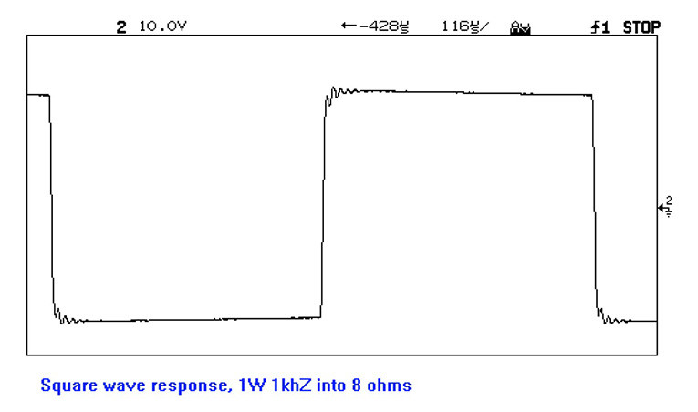
One indication of stability and frequency response is the amplifier's response to an audio-frequency square wave. Instability often shows up as ringing on the edges of the square wave, especially on amps that employ feedback through transformers. Ringing can also be the result of inherent resonances between the inductance and interwinding capacitance in the output transformer, and can give an indication of the quality of the output transformer.
Figure 9 shows an oscilloscope trace of a 1kHz square wave (with very fast edge rates on the input). You can see that although there is a slight amount of ringing, it is well damped, and the response looks very good compared to many tube amplifiers. This holds true over all output powers, with virtually no change in the waveform up to clipping.
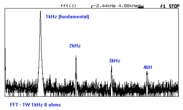
My other goal was to achieve an ideal harmonic profile, one in which the 2nd harmonic is the highest, followed by the 3rd, 4th, and so on. To measure this, I applied a 1kHz sine wave to the input and did an FFT analysis of the output, using my digital oscilloscope. The scope doesn't have very high resolution as a spectrum analyzer, but it is good enough for a relative indication of whether I met this goal.
Figure 10 gives the FFT of the output at 1W into 8Ω, showing the fundamental through 4th harmonics (the 5th and higher harmonics were in the noise, so I didn't process further). You can see that the 2nd harmonic is the highest, with the 3rd and 4th present in lesser proportions. This is the ideal harmonic profile that I was aiming for.
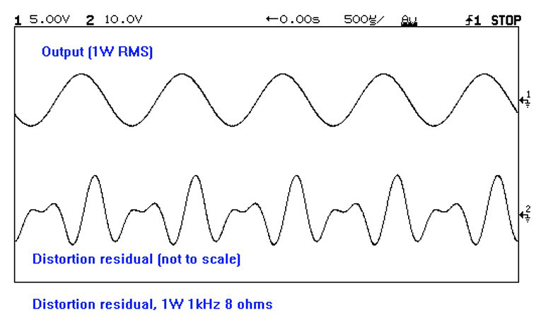
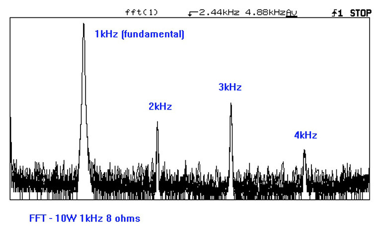
Figure 11 shows the distortion residual. This is what's left after you remove the fundamental signal (1kHz, in this case). You can see that there is mostly 2nd harmonic (2kHz) signal, as well as some 3rd harmonic (3kHz).
Figure 12 shows the spectrum at 10W. At this power level, you lose the ideal harmonic profile, as the 3rd harmonic has become larger than the 2nd. This is typical of most amplifiers - as they approach clipping, distortion becomes more symmetrical, and the odd harmonics start to increase. This is still not so bad, as there is plenty of 2nd and 4th harmonic to help mask the 3rd. Keep in mind also that the average power delivered when listening is usually less than a watt, unless you're fond of listening at hearing-damage levels, or have very inefficient speakers.
Listening Impressions
I confess to being an engineer, so I tend to put a lot of faith in the measurements. But the bottom line is how the thing sounds. This is definitely the best-sounding amplifier I’ve built! It has detailed sound and doesn’t muddy up complex music the way I’ve found a higher distortion SE amp does. It also lacks the harsh sound that I associate with a high-distortion P-P amp. Bass response is solid, not loose or boomy. I find myself drawn into the music more than with my other amplifiers. Overall, I deem it a success! aX
This article was originally published in audioXpress, April 2005.
 Resources
www.audioasylum.com - Great Internet bulletin board for all things audio. Check out the “Tube DIY” section for lots of discussion about tube circuits.
www.pmillett.com - The author’s web site, where you can download full-scale drawings of this project.
http://jianshin.myweb.hinet.net/ - James Audio’s website. In Chinese, but you can figure most of it out.
Sources
Online Metals – Metal sheet material, cut to size (800) 704-2157
www.onlinemetals.com
Digi-Key – Full-line parts distributor (800) 344-4539
www.digikey.com
Mouser Electronics – Full-line parts distributor (800) 346-6873
www.mouser.com
Handmade Electronics – Mills resistors, tube-related parts
(610) 432-5732
www.hndme.com
Allied Electronics – Motor-run caps
(800) 433-5700
www.alliedelec.com
Triode Electronics – Tubes, C-354 chokes, tube-related parts
(773) 871-7459
www.triodeelectronics.com
Antique Electronic Supply – Tubes, capacitors, tube-related parts
(800) 706-6879
www.tubesandmore.com
Angela Instruments – Tube sockets, tube-related parts
(301) 725-0451
www.angela.com
Ask Jan First (Die Wustens) – European tubes (D3a)
+49-6154-575556 (Germany)
www.askjanfirst.com
Halfin – European tubes (D3a)
+32-2-209-2981 (Belgium)
www.halfin.com