Construction was point-to-point or single-sided PCBs. If you did not have a schematic for something, you could usually trace one out with a pencil and paper. Early computer technology was more complex for the DIY community. But, you could still build a computer from scratch. Technology quickly advanced, and we benefited from some incredible capabilities.
However, it seemed that the DIY community suffered. We saw the demise of Popular Electronics (1999) and Radio Electronics (2003). Useful surplus electronics parts were harder to find. Thanks to multi-layer PCBs, surface-mount packages, and a lot of software, it became impossible to troubleshoot anything but the most basic faults in consumer electronics products. Schools spent more time on SPICE (Simulation Program with Integrated Circuit Emphasis) simulations than real world labs.
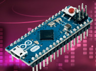
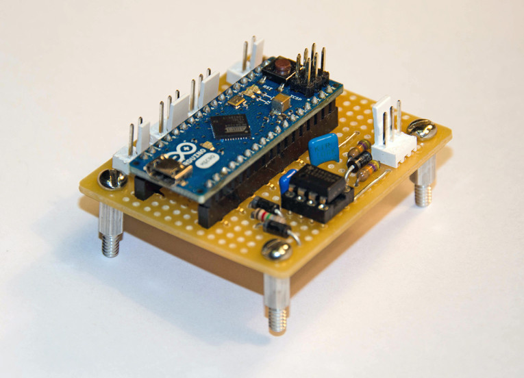
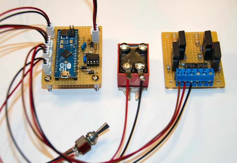
Recently, there has been a DIY resurgence described as the Maker Movement. This trend is fueled by technologies such as 3-D printing, robotics, social networks, open-source software, cheap sensors, and inexpensive microcontrollers. With the Maker Movement in mind, I thought that I would use the Arduino — a common open-source microcontroller module—to build an automatic power controller for a tube power amplifier. The resulting controller is very simple—a $25 Arduino module, a couple of dual op-amps, a few other components, and a 5-VDC power supply plus some opto-isolated switches (see Photo 1).
The controller detects an audio signal’s presence and automatically powers on the amplifier, stepping through a timed sequencing of filament, driver, and output stage power supplies. It turns off the amplifier several minutes after the audio signal is lost, helping to increase the tube life and preventing unnecessary power cycling. The controller has an override switch to manually turn the amplifier off or on, independent of the audio signal.
How It Works
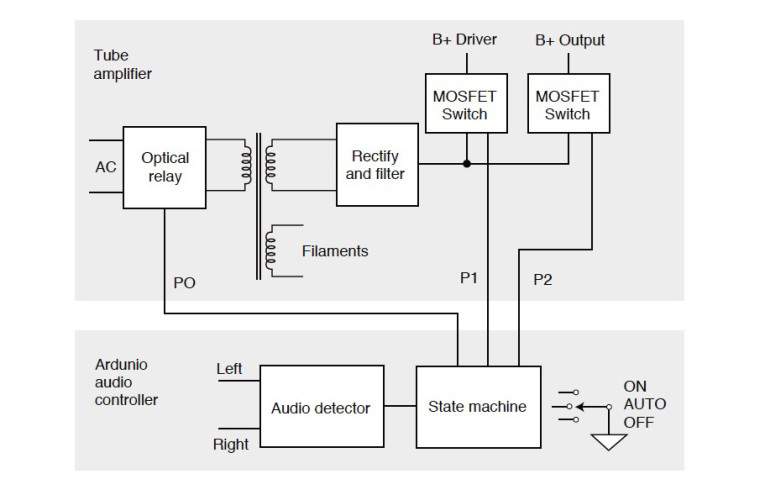
Figure 1 shows how the Arduino audio controller connects to the tube amplifier. The controller consists of an audio detector and a state machine. The state machine has three outputs that drive the switching circuits. The P0 signal switches AC to the amplifier’s power transformer using an opto-isolated, zero switching relay. The P1 and P2 signals drive the opto-isolated MOSFET switches that I will describe later in the article. The P1 signal enables the driver, while P2 enables the output stage. You do not need to use all three of the switches. If you have a solid-state amplifier just use P0. If you don’t want to separately control the driver and output stages, then don’t use P2.
Audio Detector
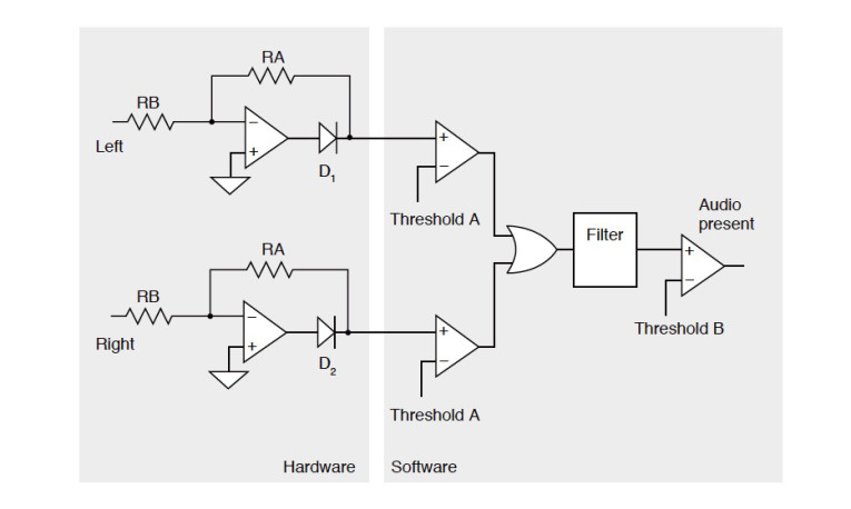
Figure 2 shows a block diagram of the audio detector. The left most portion is implemented in hardware, the remainder in software. The left and right audio signals are independently passed through precision half wave rectifiers. On the negative half cycle, the rectifier behaves like a normal inverting amplifier with gain –RA/RB except that the op-amp has to drive its output higher by the voltage drop of the diode.
When the input is positive, the op-amp output goes to ground and the diode is reverse biased. The op-amp and diode are effectively out of the signal path. There is some feed through of the input through RA and RB but without any gain. This isn’t useful, but neither is it harmful for our purposes.
The rectifier outputs are sampled with the Arduino’s built-in 10-bit ADC. The left and right channels are compared to a threshold and then logic OR’d, providing an instantaneous indication of whether there is an audio signal. The OR’d signal is passed through a digital low-pass filter and is again compared to a threshold to provide some averaging and protect against spurious noise.
You can adjust the circuit’s sensitivity by changing the gain of the precision rectifiers or by changing Threshold A and Threshold B in software. Since we don’t care about the signal’s fidelity, it does not matter if the rectifier saturates on large input signals. The gain can be set fairly high to provide good sensitivity.
State Machine
Once we have an indication that audio is present, we use a software state machine to implement the power sequencing. When audio is detected, the P0 output is enabled, and we start a counter that waits 8 s before enabling P1 and then a further 1 s before enabling P2. Once audio has been absent for 120 s, we disable all three outputs. Manual override switches are provided. When in the manual off position, the amplifier instantly turns off regardless of the presence of audio. When in the manual on position the amplifier turns on and goes through the normal power-up sequencing.
Power Amplifier Control
To switch the AC power (P0), I used an opto-isolated “relay.” It has a zero crossing feature that reduces turn on transients, which is especially important with toroidal transformers. The control input does not need an external current limiting resistor and is directly connected to the P0 Arduino output port. To switch the B+ supply, I used power MOSFETs with an opto-isolated driver.
When I started this project, I searched for a driver that was simpler than the discrete circuit I had previously designed. That yielded the FDA217 driver chip from IXYS. Quoting from its datasheet: “The FDA217 is a dual photovoltaic MOSFET driver. Each independent driver consists of an LED that is optically coupled to a photodiode array. The driver output is controlled by means of the highly effective gallium-aluminum-arsenide (GaAlAs) infrared LED at the input. When the input current is applied to the LED, the light emitted activates the photodiode array, and generates the voltage at the output.
The photodiode array is capable of generating a floating power source with voltage and current sufficient to drive high-power MOSFET transistors. Each photodiode array contains an integrated turnoff circuit that discharges the external MOSFET gate when LED current is removed. This eliminates the need to use external components to facilitate the discharge. The optically coupled technology provides 3,750 VRMS of input to output isolation.”[1]
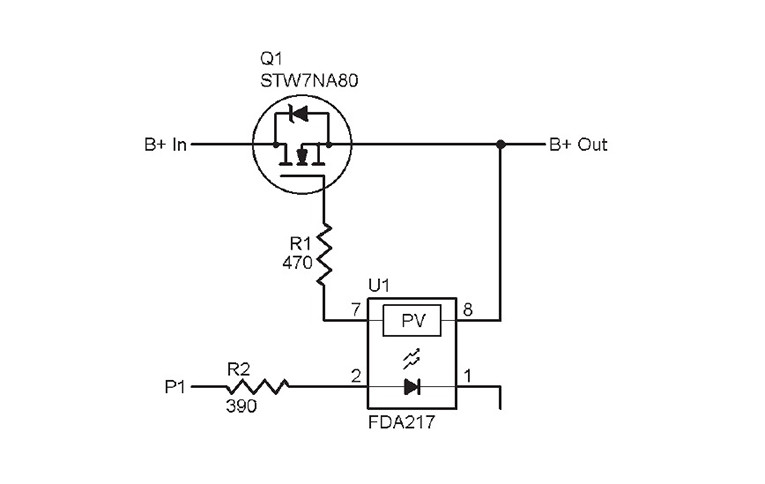
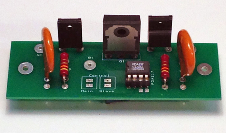
At $2.50 each, the FDA217 chips make extremely simple and cost effective drivers. Without heat sinking, Q1 can safely pass a few hundred milliamps. The FDA217 is operated at 10-mA forward current through the 390-Ω series resistor, R2 (see Figure 3). The 470-Ω resistor R1 is a gate stopper and should be as close as possible to the gate of the MOSFET. The MOSFET is an N-channel enhancement mode device.
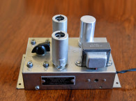
I used surplus STW7NA80s with an 800-V drain to-source voltage rating. You can substitute other devices that are compatible with your amplifier’s voltage and current needs. Follow normal high voltage safety precautions when working with the B+ circuits. Power off and ensure all capacitors are safely discharged before working on any high voltage circuit (see Photo 2).
Putting It Together
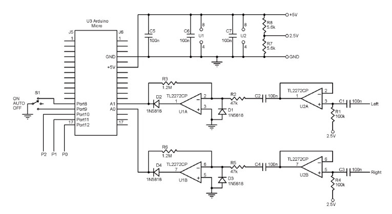
Figure 4 shows the schematic for the Arduino audio controller. You can buy the Arduino from multiple online sources. There are several poor quality copies for sale. I recommend using a reputable supplier and paying a couple more dollars. I used the Arduino Micro version for its small size (4.88 cm × 1.77 cm). I have provided pin numbers for the Micro but you can use any version. Power for the controller is provided by a small 5-VDC cellphone charger.
Op-amp U2 is an AC-coupled unity gain buffer. It isolates the amplifier audio input from the precision rectifier. The rectifier’s input impedance dramatically varies for the positive and negative inputs, which could cause distortion if it was directly loading the audio input.
Op-amp U1 is the precision rectifier with a gain of roughly 25. Schottky diodes D1 and D3 provide input protection for the op-amp. The op-amps are rail-to-rail devices suitable for 5-V single-ended operation. To aid in debugging, the built-in LED on the Arduino board (port 13) is turned on when audio is detected, and a square wave is output on port 7 at the sample frequency (2 kHz).
Software
In addition to a soldering iron, you will need a computer to upload the software into the controller. Arduino has an excellent website and online forum if you need additional help (see Resources). Here are step-by-step instructions.
• Follow the instructions at http://arduino.cc/en/guide/windows to download the Arduino Integrated Development Environment (IDE) software. Then connect the Arduino to your computer and install the device drivers. On my machine, I needed to tell Windows 8 to disable driver signature checking to get the driver to properly install.
• In the IDE, under the Tools menu, select the model of board you are using. Then, choose the first entry from the Serial Port menu (you may need to repeat the serial port step each time you reconnect the Arduino to the PC).
• Download the “sketch” (software) for the audio controller from the Supplementary Materials section of the audioXpress website.
Open the sketch using menu commands File, Open…
• Upload the sketch to the Arduino using menu command File, Upload
• Remove the USB cable and install the Arduino in the amplifier
• If you want to implement different delays then simply change the definitions in the “DelayP0”, “DelayP1” and “DelayOff” constants before you do the File, Upload.
Taking It Further
The Arduino controller can easily be extended to other functions. In a audioXpress future article, I will explain how to add amplifier-over-temperature shutdown protection and how to incorporate a software version of my earlier bias and balance meter design. The article will also include a PCB design for the controller.
This article was originally published in audioXpress, February 2015.
| Designation | Part Number | Description |
|---|---|---|
| U1, U2 | TLC2272 | rail-to-rail op-amp |
| U3 | Arduino microcontroller | |
| D1-D4 | IN5818 | Schottky diode |
| R1, R4 | 100 kΩ, 1/8-W resistor | |
| R2, R5 | 47 kΩ, 1/8-W resistor | |
| R3, R6 | 1.2 MΩ, 1/8-W resistor | |
| R7, R8 | 5.6 kΩ, 1/8-W resistor | |
| C1-C7 | 100 n | |
| S1 | 3PST rotary switch or center off SP2T toggle switch |
| Designation | Description |
|---|---|
| Q1 | ST W7NA80 N-channel MOSFET |
| U1 | FDA217 opto-isolated MOSFET driver |
| R1 | 470R, 1/8-W resistor |
| R2 | 390R, 1/8-W resistor |
Project Files: To download additional material and files, visit
audioxpress.com/page/audioXpress-Supplementary-Material.html.
Reference
[1] IXYS, Integrated Circuits Division, FDA217 Dual Photovolatic MOSFET Driver datasheet, www.ixysic.com/home/pdfs.nsf/www/FDA217.pdf/$file/FDA217.pdf.
Resources
Arduino, arduino.cc.
M. Driedger, “An Accurate Bias Meter for Push Pull Output Stages,” audioXpress, July 2012.
B. Kernighan and D. Ritchie, The C Programming Language, Prentice-Hall, 1978.
Sources
FDA217 driver chip
IXYS Corp. | www.ixys.com
70S2-04-B Opto-isolated relay
Magnecraft (now Schneider Electric) | www.schneider-electric.com
TLC2272CP Op-amp
Texas Instruments, Inc. | www.ti.com
See next page for Arduino Software Basics