Constant Voltage vs Constant Current
Constant voltage (rather than constant current) is the most common vacuum tube heater drive technique. Power transformers for tube amplifiers are commonly made with 6.3-V or 12.6-V windings to drive the amplifier’s tube heaters in parallel. Powering heaters with a constant current can require an inconvenient voltage level.
The heater supply voltage must be higher than the sum of the tube heater voltages you are driving in series. However, that supply voltage cannot be excessively large or too much power will dissipate in the current source.
Because of these voltage-level constraints, voltage drives have been (and probably will continue to be) the most common heater driver. However, current drives have some advantages. Constant-current heater drives have three advantages over voltage drives:
• In-rush current surges are eliminated and power dissipated in the heater during warm-up does not exceed the heater’s nominal operating power.
• Because the heaters are usually wired in series when driven with a constant current, you can use the voltage across the last heater in the string (the ground-referenced heater) as a signal to delay the B+ voltage turn-on until the heaters are warmed up.
• Since your B+ voltage doesn’t turn on until the ground-referenced heater voltage reaches full level, if a tube is left out of its socket, the amplifier will not start up, avoiding unintended behavior.
Take a look at the first advantage — the elimination of power surges at turn on. Figure 1 shows a comparison of measured power (in watts) dissipated in a 12AX7 tube’s heater when it is driven using either a constant DC voltage or constant DC current.

After a 12AX7 is warmed up, its heater nominally dissipates about 1.8 W (i.e., 150 mA × 12 V). Note that when the constant voltage drive is switched on (at time = 0), the power dissipated in the heater spikes to almost 8 W and then exponentially decays to its nominal operating level as the heater warms up and its resistance increases. When the heater is driven with a constant current, this turn-on power surge is eliminated and the warm-up power never exceeds the heater’s nominal operating power.

Figure 2 shows the concept of driving heaters in series with a constant current. With the current source set to its proper value, as the heater warms, the voltage developed across each heater increases until it plateaus at the heater’s rated voltage.
Current Source
Figure 3 shows a schematic of a 150-mA current source driving two 12-V heaters. This current source is to first order, temperature-compensated. I have also used non-temperature-compensated current sources (eliminate U1 and Q2 and recalculate R1’s value to be about 4 Ω). But, I found that if the components are located in close proximity to one another, the pass transistor (Q2) can heat up the voltage sense transistor (Q3) and reduce the heater current.

The circuit is very straightforward. R4 pulls current out of Q1’s base, tending to turn it on. The diode-connected transistor Q2 simply temperature compensates for Q3’s base-emitter voltage drop. U1 is a band-gap voltage reference. When the voltage drops (due to heater current) across R1 reaches U1’s voltage (1.23 V), Q3 tends to turn on, which feeds current into Q1’s base (tending to turn it off). The circuit quickly reaches equilibrium at a current flowing through R1 equal to 150 mA (i.e., 1.23 V/8.2 Ω). R2 enables you to use a slightly higher value resistor for R1 and trim it down to achieve precisely your desired current.
Although R2, R3, and R4 can be surface-mount resistors, R1 is specifically called out as a 0.25-W through-hole part because its power dissipation is about 90 mW. If R1 heats up significantly, its resistance will increase and reduce the heater current.
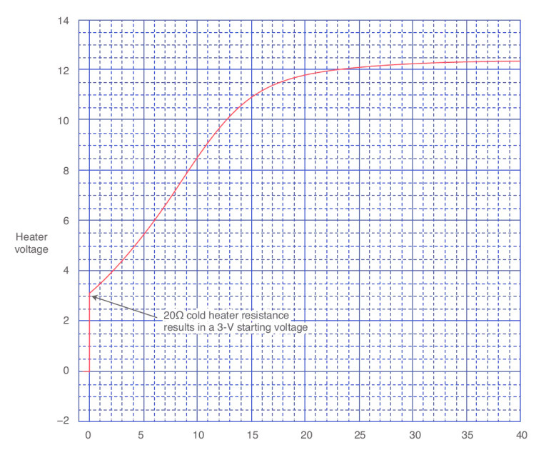
Q2 and Q3 can be small SOT-23 or TO-92 packages, but Q1 (the pass transistor) needs to be a TO-220 device because it dissipates almost 1 W. Figure 4 is a plot of voltage across a 12AX7 (12-V) heater when driven with a 150-mA constant-current source. The heater has a cold resistance of about 20 Ω, so the voltage across the tube initially jumps to 3 V. The voltage slowly rises because the heater resistance increases as it warms up. The nominal working resistance is about 80 Ω.
Delay Tactics
Figure 5 shows the second feature a constant-current drive offers — the ability to use the heater voltage as a signal to delay turn on of your B+ voltage until after the tube heaters are warmed up. You can compare the rising voltage developed across the ground-referenced heater against a reference voltage. When the heater voltage increases above the reference voltage, the amplifier’s B+ voltage is enabled using either a solid-state switch or relay. The signal can also drive a “power on” indicator (e.g., an LED) to signal to the user that the amplifier is warmed up.
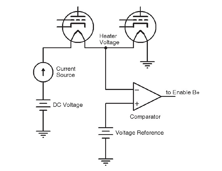
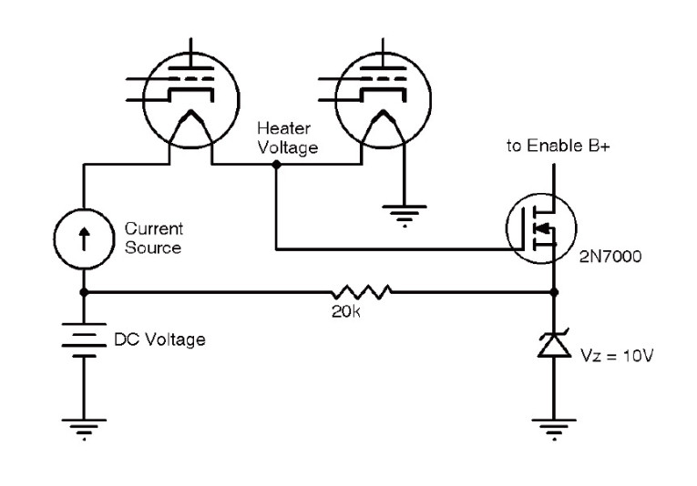
Figure 6 shows a schematic of a circuit I used in this application. When the voltage at the top of the ground-referenced heater (labeled “Heater Voltage” in Figure 6) exceeds about 12 V (i.e., the 10-V Zener voltage + the threshold voltage of the 2N7000 N-channel MOSFET), the 2N7000 transistor turns on. This pull down can be used to drive a P-channel pass transistor or relay driver to enable the circuit’s B+ voltage.
Driving tube heaters with a constant current is not a new idea, but it’s an electrically interesting way to be kind to our thermionic friends. aX
This article was originally published in audioXpress, May 2014.
About the Author
Bill Reeve is a technical program manager at Google in Mountain View, CA. He has graduate engineering degrees from the Colorado School of Mines and the University of California, Berkeley. He also earned his Masters degree in Electrical Engineering from Santa Clara University.