After surveying the field, it became clear that the products from THAT Corporation offer superior performance to any of their competitors’ chips. Like IC op amps, these devices are capable of varying degrees of performance depending on the quality of the passive components used in the associated circuitry, and power supplies. This article describes how to get the most from these chips. Anyone intending to use them should download the datasheets for these devices on THAT’s website (www.thatcorp.com).
During the October 2005 convention of the Audio Engineering Society (AES), I attended a seminar given by Bill Whitlock, President of Jensen Transformers, on “Grounding and System Interfacing.” I gave a report on this presentation in the January 2007 issue of aX.1 Near the end of his presentation, Whitlock described the InGenius series of balanced line receiver ICs he designed for THAT Corporation. Whitlock developed a unique bootstrapping technique that raises the common-mode input impedance into the megohm region, while maintaining reasonable values for the input bias return resistors.
Raising the values of these resistors will degrade noise performance, but Whitlock’s clever topology maintains low noise, keeping the resistor values low but the common-mode input impedance very high. The three chips in the InGenius line are the THAT 1200, 1203, and 1206, which are identical except for gain: 0dB for the 1200, -3dB for the 1203, and -6dB for the 1206.
THAT Corporation gave a seminar at the October 2007 AES convention covering — among other things — their OutSmarts line of balanced line drivers. I reported on this seminar in the June 2008 issue of aX.2 The OutSmarts line, which includes THAT’s 1606 and 1646 devices, incorporates a dual feedback loop design which prevents excessive ground currents typical of cross-coupled output stages when clipping into single-ended loads. In fact, when driving single-ended loads, the OutSmarts devices yield their lowest noise and distortion when one output leg is grounded.
THAT 1200 Offset
The maximum output offset voltage for the THAT 1200-series chips is specified as 10mV, and most samples I’ve measured tend to run between 4 and 7mV. This may be fine for some applications, but, in the two locations I use them in my archival phono preamplifier, they are followed by DC-coupled gain stages. The typical “pro” audio solution to DC offsets is to fill equipment with electrolytic coupling capacitors, which is simply unacceptable in a piece of high-end audio equipment.
I e-mailed Gary Hebert, Chief Technology Officer at THAT, and asked whether it was possible to null the 1200’s offset with a DC-servo integrator. He said that it should be possible to do so, applying the servo output to the Reference pin (pin 1). He noted one caveat: If you follow the integrator with the usual resistive attenuator, you’ll seriously degrade the common mode rejection of the chip. As you’ll see shortly, the 1200-series chips actually contain the resistive divider internally, but the resistor values are such that the integrator must have a considerably longer time constant in order to achieve the same -3dB point for the circuit as it would in a more conventional implementation. Integrators configured as DC servos for audio amplifiers have received scant coverage in electronics textbooks and periodicals. The best tutorial on their design was published by Walt Jung in Analog Devices’ massive 1993 Systems Applications Guide.3
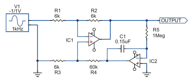
Figure 1 shows an op amp configured as a unity-gain inverting amplifier with DC-servo control of the circuit. The unity-gain inverter consists of IC1, R1, and R2 (Gain = R2/R1). IC2 is configured as an integrator, with its time constant determined by R5 and C1 (T = RC). In this application, the integrator functions as a DC servo amplifier, applying DC feedback to the non-inverting input of IC1 through the resistive divider (attenuator) R3 and R4.
Following Jung’s guidelines, R3 is equal to R1, and R4 is ten times the value of R2. The -3dB point for the entire circuit should be about 1/100 of the lowest audible frequency—usually 20Hz — in order to minimize rolloff and phase shift within the audible spectrum. R5 and C1 are selected for reasonable values; R5 will normally be at least 500k and the R5/C1 combination should yield a -3dB point for the entire circuit of around 0.2Hz.
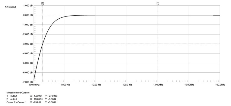
Following the math outlined in Jung’s article, which I won’t repeat here, the integrator time constant for Fig. 1 is 0.15 seconds and the -3dB point for the entire circuit is 0.19Hz. The simulated frequency response for this circuit is shown in Fig. 2, which verifies that the calculations are correct.
Circuit Simulation
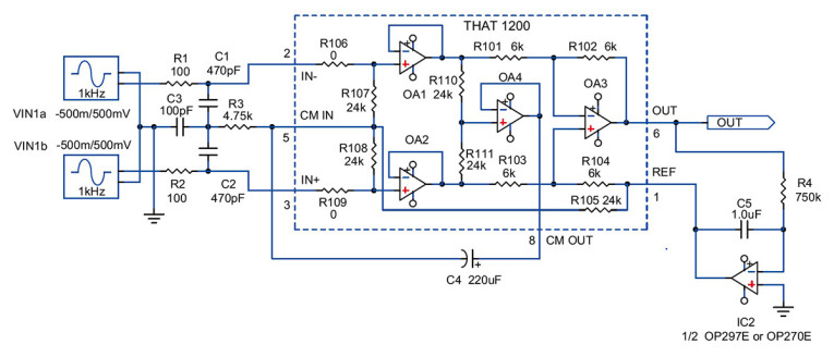
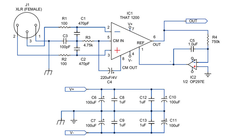
Figure 3 shows a simulation of the THAT 1200 balanced line receiver in a complete working circuit, including RFI protection at the input, as recommended in the manufacturer’s datasheet, which also shows methods for ESD (electrostatic discharge) protection, if needed. Internally, the THAT 1200-series chips have diodes that provide “modest protection against common low-voltage ESD incidents.”
The manufacturer’s own testing has shown that repeated exposure to levels of ESD above 1kV through the non-inverting and/or inverting inputs can degrade the common-mode rejection and, ultimately, cause failure of the chip. If your application may expose the chip to high levels of ESD, I recommend using the protection. Note that the datasheet shows one method for the 1200 and another for the 1203 and 1206, because the 1203 and 1206 allow input signals that swing higher than the supply rails.
The circuit inside the dashed line is the THAT 1200 equivalent circuit, which is shown on the first page of the datasheet. The type of op amp used in the simulation isn’t critical if all you need to do is verify that the circuit works with the servo connected, and check the low-frequency -3dB point. The generic “Op-Amp 5” model found in most Spice-based simulation programs will work fine. When I asked Gary Hebert what op amp would be suitable for simulating the THAT 1200, he suggested a 5532. Bear in mind, however, that the performance of the THAT 1200 is an order of magnitude better than the dated 5532, with higher slew rate (12V/µS versus 9V/µS for the TI NE5532A), and wider bandwidth (22MHz versus 10MHz).
Both chips will operate with rail voltages higher than the standard +/-18V. The absolute maximum rating for the NE5532A is +/-22V, compared to +/-20V for the THAT 1200. So, the NE5532A (and the single NE5534A) will allow you to run your simulation at the full supply rail capability of the THAT 1200. A safety margin is always desirable for long-term reliability; the +/-20V maximum rating ensures that longterm operation at +/-18V will be no problem.
Note the output stage consisting of OA3 plus the resistors R101 through R104. R101 and R102 are the functional equivalents of R1 and R2 in Fig. 1. Normally, the reference pin (1) on the THAT 1200 is grounded, so OA3 functions as a unity-gain differential amplifier with a single-ended output. With a DC-servo integrator connected as shown in Fig. 3, the reference pin is still effectively at signal ground. R103 and R104 become the functional equivalents of R3 and R4 in Fig. 1. But, R104 is internally set at 6k, the same value as R102. If these two resistors aren’t the same value, the common-mode rejection of the chip will be severely compromised. So, R104 won’t be ten times the value of R102.
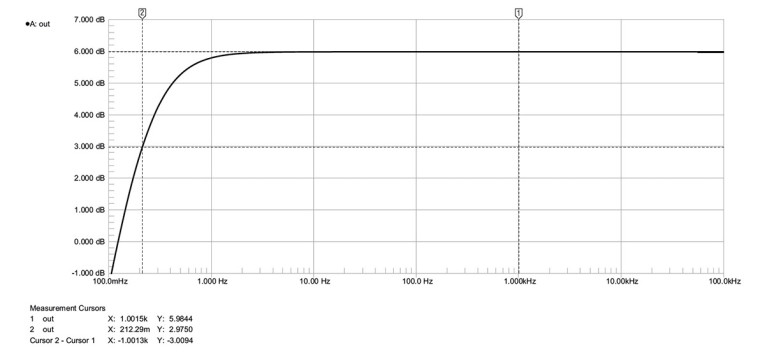
In order to make the -3dB point for the entire circuit similar to Fig. 1, the integrator time constant will need to be considerably longer. C5 and R4, 1µF and 750k, yield an integrator time constant of 0.75sec, which produces a -3dB point for the entire circuit of 0.2122Hz. The simulated frequency response of this circuit is shown in Fig. 4, again verifying that the calculations are correct.
The THAT 1203 and 1206, with gains of -3dB and -6dB, respectively, may be desirable in applications where higher input voltages are likely. In the 1203, R101 through R104 are the same values as in the 1200. But, in the 1206, R101 and R103 are 7k, with R102 and R104 set at 5k. This is no problem for the servo, since the math is a wash. The -3dB point for the circuit using a 1206 will be the same as it is with the 1203 and 1200. So, you can swap 1200-series chips without having to re-calculate the integrator R/C values. In the 1203 and 1206, R106 and R109 are set at 7k, and R107 and R108 are 17k. These will obviously have no effect on the DC servo, but they do affect the overall gain of the device.
Servo Amp Choices
The choice of op amp for the servo amplifier will depend on what’s most important in your application — the lowest possible noise or the lowest possible output offset. Noise of the THAT 1200 is specified at an impressive -107dBu, so any servo amplifier has the potential of degrading its excellent noise performance. Gary Hebert suggested an OP27.
For a stereo pair, I prefer to use a dual op amp to conserve space, so I chose Analog Devices’ OP270E. As noted in the datasheet, the OP270E offers comparable performance to the OP27E. With the OP270, I measured noise at -96dB relative to 2V
RMS out. Input offset voltage of the OP270E is extremely low—typically 10µV — but input bias current is 5nA. So, the output offset of the circuit will be somewhat affected by the source impedance, set by R4, which is 750k. Output offset of the THAT 1200 using the OP270E usually runs between 1 and 2mV, which may be sufficiently low for many applications. It wasn’t for one of mine, however, so I decided to try the OP297E, which I have used in many other DC servos.
The OP297E has higher input offset voltage than that OP270E—25µV— but it also has ultra-low input bias current, typically 20pA. Output offset from the THAT 1200 using the OP297E is usually less than 0.2mV. Although the OP297E is noisier than the OP270E, noise performance of the THAT 1200 is degraded no more than 2dB compared to the OP270E. For applications where ultra-low output offset is necessary, the OP297E is the best choice. Digi-Key carries only the ceramic DIP packages for the OP297E and OP270E (“Z” suffix); the plastic DIP version (“P” suffix) are certainly fine, if you can find them.
THAT 1200 Construction
In choosing parts for these circuits, I avoided components containing steel, because I believe that non-permeable materials have a positive effect on the sound. Figure 5 shows a single-channel THAT 1200 balanced line driver circuit with DCservo control, input XLR connector, and power supply bypassing. The DH Labs D4 prototyping board sold by Old Colony is ideal for building a stereo pair using a dual op amp for the servo amplifier.
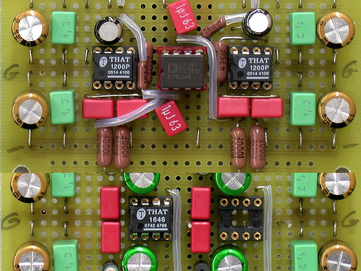
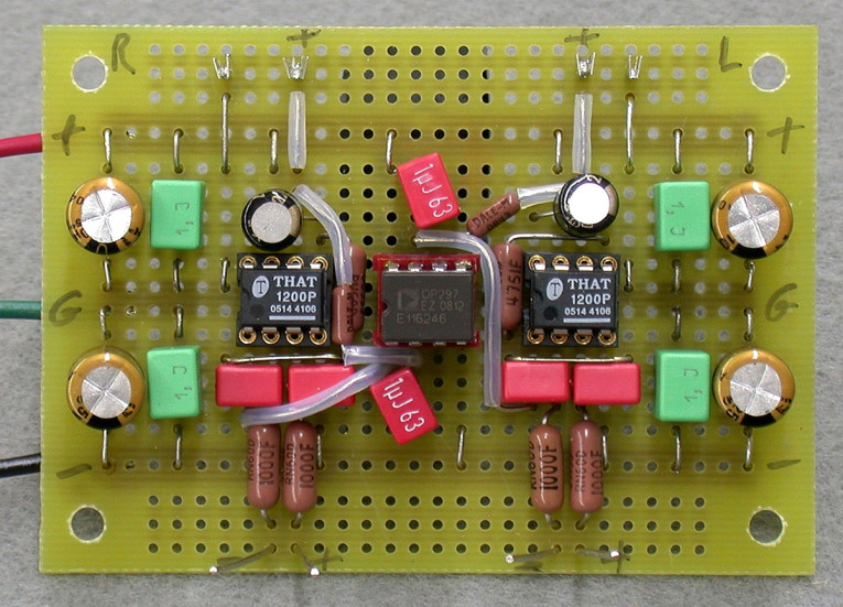
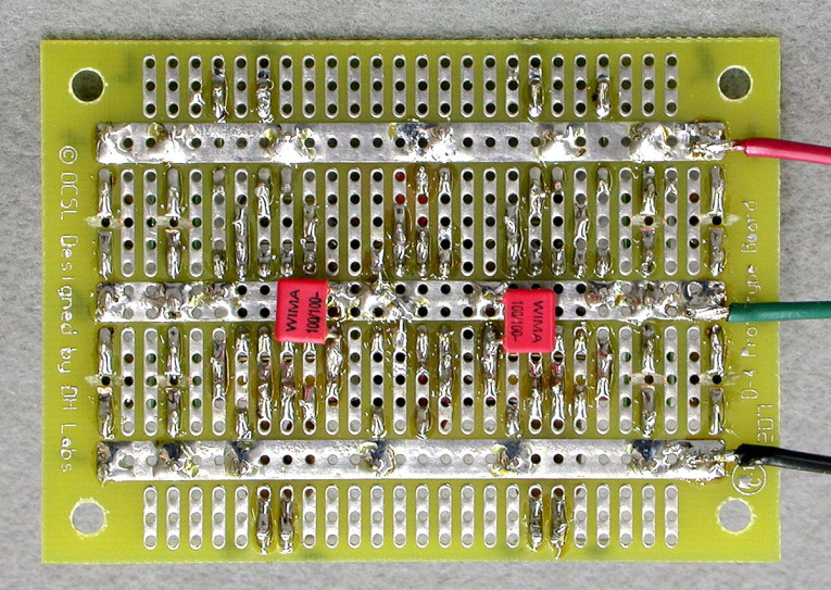
Photos 1 and 2 show a recommended layout for the circuits; the temporary leads are attached for testing. Mount the supply bypass capacitors on either end of the board. You’ll need to cut traces under these capacitors to avoid shorting them out (Photo 2), and install jumpers to make connections to the supply rails and the center ground bus. I recommend Nichicon FG-series electrolytics bypassed with Wima or Roderstein polyesters.
I used Mil-Max machined-pin, gold-plated IC sockets for the THAT 1200 chips and the servo op amp, because I was still experimenting after my boards were built. Consider them optional. If you wish to experiment with different servo op amps, or the three 1200-series chips, I suggest soldering the ICs to an Aries gold-plated header. This gives a gold-on-gold connection when the chips are mated with the IC sockets.
Capacitors C1 through C3 are Wima FKP2-series polypropylenes. C3 is the only part that won’t fit on the component side of the board. Mount it on the foil side, as shown in Photo 2. THAT Corp. specifies a 4V capacitor for bootstrap capacitor C4. The best type I’ve found is a Black Gate PK-series sold by Michael Percy Audio. Unfortunately, Rubycon no longer manufactures the Black Gate line, but Percy still has them in stock. When these are no longer available, I suggest substituting a Nichicon KZseries. The smallest available is 25V, but it should still fit. Servo capacitor C5 is the same Wima or Roderstein polyester type used for power supply bypassing.
All resistors are Vishay/Dale RN60 metal film types except for R4, which can be an RN55. I consider these to be good entry-level high-end audio resistors, particularly since all of the RN60 types still seem to be made with copper end caps (copper leads are specified, but the datasheet makes no mention of the end caps). Some of the RN55 types have been coming through with steel end caps, but the current through the 750k resistor is so low that the magnetic effects are of little consequence. Use sleeving over any leads that may touch others.
If your application demands more exotic resistors, by all means use them. The PR9372-series from Precision Resistive Products are designed specifically for audio applications and have gained an excellent reputation in high-end audio circles. Parts Connexion carries a large assortment of these resistors at very reasonable prices. I prefer Neutrik XLR connectors with gold-plated contacts.
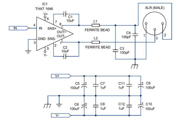
Balanced Line Driver
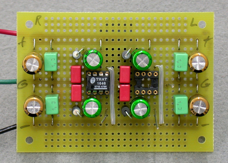
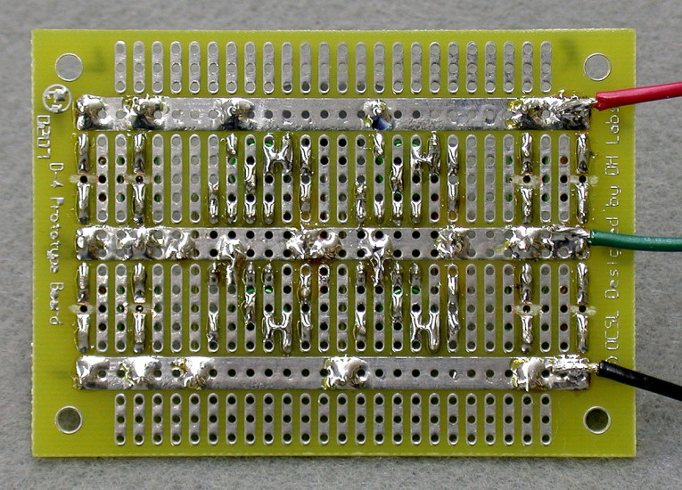
THAT’s 1646 Balanced Line Driver is a very simple IC to implement, requiring very few external components. A complete schematic, including RFI protection and power supply bypassing, is shown in Fig. 6. A stereo pair will fit on the D4 prototyping board with room to spare; IC sockets are optional. Use the same types of capacitors for supply bypassing that I recommended for the 1200. Locate them on either end of the board, cutting the PC traces under the capacitors, and installing jumpers to make connections to the supply rails and ground bus (Photos 3 and 4, which also show leads attached for testing).
The common-mode offset protection capacitors C1 and C2 ensure very low output common-mode voltage offset—typically +/-3.5mV (maximum +/-15mV, though most samples I’ve used were within the typical range). Without these capacitors, typical offset will be +/-50mV, and can be as high as +/-250mV; even +/-50mV is unacceptably high for most applications. Use very high quality non-polar electrolytic capacitors, such as the Nichicon ES series. A film capacitor would be ideal, but the physical size of a 10µF film cap, at any readily-available voltage, makes this an impractical choice. Use the Murata ferrite bead inductors and Wima FKP-2-series polypropylene capacitors for RFI protection, L1, L2, C3, and C4.
The 1646 incorporates a proprietary internal protection scheme which should be sufficient for the levels of ESD encountered in most normal field situations. It is possible, however, for any balanced output to be accidentally plugged into a microphone preamp with +48V phantom power. The 1646 datasheet shows an external scheme for protecting the chip from such hazards. If you think you need it, by all means use it.
I mentioned power supplies only in passing at the beginning of this article. Suffice to say, these chips will give their best performance with high-quality, regulated power supplies. The THAT 1200 and 1646 balanced line receivers and drivers represent the state-of-the-art in active, IC-based balanced inputs and outputs. With a proper operating environment they offer excellent performance at very reasonable cost. aX
This article was originally published in audioXpress, June 2010.
References
1. Galo, Gary, “Grounding and System Interfacing,” audioXpress, Jan. 2007, pp. 28-29.
2. Galo, Gary, “Is SACD Doomed? — New York AES 2007: A Convention Notable for What Wasn’t There,” audioXpress, June 2008, pp. 27-30.
3. Jung, Walt, “Audio Preamplifiers, Line Drivers and Line Receivers,” System Applications Guide, Analog Devices, Inc., 1993, pp. 8-93 to 8-97.
Vendors
Digi-Key Corporation - www.digikey.com
Michael Percy Audio - www.percyaudio.com
Mouser Electronics - www.mouser.com
THAT Corporation - www.thatcorp.com
Parts Connexion - www.partsconnexion.com
Parts Lists
THAT 1200 Line Receiver Board
(Quantities are for a 2-channel stereo board)
(1) DH Labs D4 Prototype Board (Old Colony Sound Lab #PCBD-4)
(2) THAT 1200, 1203, or 1206 Balanced Line Receiver IC (IC1; Mouser #887-1200P08-U,
887-1203P08-U or 887-1206P08-U; see text)
(1) Analog Devices OP297E Dual Op Amp (IC2; Digi-Key OP297EZ-ND) – or – OP270EZ (Digi-Key OP270EZ-ND)
(3) Mill-Max 8-Pin Low-Profile IC Socket (Mouser 575-113308)
(3) Aries 8-Pin DIP Header (Mouser 535-08-600-11; Optional – see text)
(4) Wima 470pF/100V, 5% Polypropylene Capacitor (C1, C2; Mouser 505-FKP2470/100/5)
(2) Wima 100pF/100V, 5% Polypropylene Capacitor (C3; Mouser 505-FKP2100/100/5)
(2) Black Gate PK-Series 220????F/4V Electrolytic Capacitor or
Nichicon KZ-Series 220????F/25V Electrolytic Capacitor (C4; M. Percy)
(4) 100Ω, 1% Vishay/Dale Metal Film Resistor (R1, R2; Mouser 71-RN60D-F-100)
(2) 4.75k, 1% Vishay/Dale Metal Film Resistor (R3; Mouser 71-RN60D-F-4.75k)
(2) 750k, 1% Vishay/Dale Metal Film Resistor (R4; Mouser 71-RN55D-F-750k)
(4) Nichicon 100????F /25V FG-series Electrolytic Capacitor (C6-7, C10-11); M. Percy)
(5) Wima – or – Roederstein 1.0????F /63V Polyester Capacitor
(C5, C8-9, C12-13; Mouser #505-MKS21.0/63/5 or #75-MKT1817510064)
(2) Neutrik NC3FD-L-B-1 Female, Chassis-mount XLR Connector (Mouser 568-NC3FD-L-1-B)
THAT 1646 Line Driver Board
(Quantities are for a 2-channel stereo board)
(1) DH Labs D4 Prototype Board (Old Colony #PCBD-4)
(2) THAT 1646 Balanced Line Driver IC (IC1; Mouser 887-1646P08-U)
(2) Mill-Max 8-Pin Low-Profile IC Socket (Mouser 575-113308)
(2) Aries 8-Pin DIP Header (Mouser 535-08-600-11; Optional – see text)
(4) Nichicon ES-series 10????F/50V Non-Polar Electrolytic Capacitor (C1, C2; M. Percy)
(4) Wima 100pF/100V, 5% Polypropylene Capacitor (C3, C4; Mouser 505-FKP2100/100/5)
(4) Murata Ferrite Bead Inductor (L1, L2; Mouser 81-BL01RN1A1D2B)
(4) Nichicon 100µF/25V FG-series Electrolytic Capacitor (C5-6, C9-10); M. Percy)
(4) Wima or Roederstein 1.0µF /63V Polyester Capacitor
(C7-8, C11-12; Mouser #505-MKS21.0/63/5 or #75-MKT1817510064)
(2) Neutrik NC3MD-L-B-1 Male, Chassis-mount XLR Connector (Mouser 568-NC3MD-L-1-B)