
More and more, the pro audio market leans on system approaches. That is, rather than trying to patch together parts from various manufacturers to achieve a coherent system with desired performance attributes, installers and touring sound professionals now have the option of using a single manufacturer solution with designed-in compatibility and a vastly simplified setup. Central to this concept is the integration of communication between components and that implies nontraditional combinations of component functionality.
In its top of the line X and K Series pro sound amplifiers, Powersoft Audio has incorporated an integrated systems approach. The communications control via plug-in modules enable the amplifiers to “talk” to one another as well as receive commands and data from a central source. This does not come at the cost of performance or efficiency, which are the driving factors in their designs.
Recherche du Temps Perdue
When I was a much younger lad, I worked as a “grunt” laborer during some large installations. The grunt laborers lugged racks of amplifiers, patch bays, mixers, equalizers, and limiters, which was probably good for muscular development but bad for our backs! When we were done, the power consumption was impressive. We also had walkie-talkies, so we could communicate from selected positions in the audience area to the guy (and it was always a guy) setting up the sound balances. I felt sorry for touring crews who had to go through this same back-breaking and inconvenient process every night.
Just as the laptop computer I use now is far smaller, lighter, more energy-efficient, and dramatically more powerful than the room-filling mainframe computer I used then, the electronics used in touring and installation have undergone a similar metamorphosis and evolution.
If I were to give an illustrative example of several decades of technical progress with a 21st-century sensibility, the Powersoft Audio amplifiers would be a prime candidate. Back then, we could get lots of power and low distortion, but we weren’t really concerned with ecology or energy efficiency. Frankly, I couldn’t even have imagined the versatility and control that is possible today.
As a bit of background, Powersoft Audio is an Italian company based in Scandicci (Florence) and founded in 1995. Its original claim to fame was the introduction of Class-D amplification to the notoriously conservative pro touring and installation markets. As a company philosophy, Powersoft Audio strives to define the technological edge of its markets rather than follow trends. Its current R&D efforts focus on the amplifier technology’s interaction with “adjacent domains,” especially the world of transducers and the actual effects of this interaction in the acoustical domain.
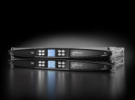
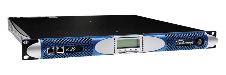
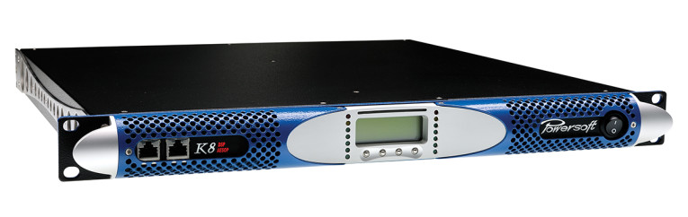
As a consequence, some of the technologies are more complex than simple amplifiers. Powersoft Audio’s flagship X and K Series amplifiers exemplify this approach for touring (see Photo 1). Multi-channel systems intended for installation are marketed under the Ottocanali, Quattrocanali, and Duecanali Series. Let’s examine the technologies involved and how they impact the end user.
Green is the Color of my Amplifier
In amplification, power is a two-edged sword. For performance, we want to maximize the power out, but for economy (and ecology) we want to minimize the power in. We also want to minimize the overhead energy expenditures (e.g., transportation and thermal management, which do not add value to the product use). Powersoft Audio has taken a three-tier approach to minimizing energy expenditure, and touts its products as being green. The basic elements include low weight, heat management, and power factor management.
The Amplifier
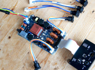
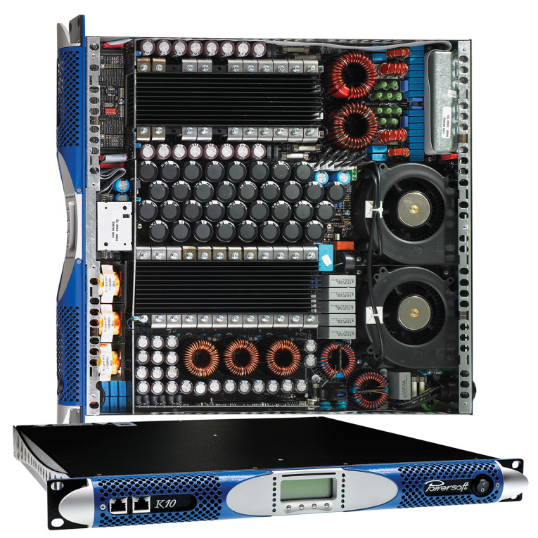
Low weight and heat management (which is a proxy for efficiency) are achieved in two basic ways, the use of Class-D amplification and “smart” switching power supplies (see Photo 2). The former method, often inaccurately referred to as “digital amplification” (perhaps the letter D fools people), uses a fixed frequency triangle wave and comparator to convert the analog input to a pulse width modulated (PWM) signal. The signal is then filtered to restore a bandwidth-limited amplified replica of the input.
Class-D amplification achieves its high efficiency by running the output devices (the highest energy-use location in an amplifier) in a binary mode (i.e., fully on or fully off). When “off,” the output devices’ current is nearly zero, so there’s essentially no power dissipation. When “on,” the current is high, but the voltage across the device is low (about 1 V or less), so the power dissipation is quite low. Most of the power dissipated is during the transition from off to on and vice versa; since that time is very short (microseconds), the efficiency (power out to the speaker vs. power wasted as heat) can be quite high, with better than 90% being common.
Powersoft Audio claims 95% to 99% efficiencies. By comparison, a conventional amplifier running Class B has a maximum theoretical efficiency of 78%. Class D is not a new concept (the first example I read about used vacuum tubes) and is quite commonplace today. But, Powersoft Audio has been commercially using Class D in professional amplifiers for nearly 20 years.
The conventional method of bandwidth limiting the PWM’s output to convert it to a noise-free analog output is the use of an LC (inductor capacitor) low-pass filter with a corner frequency well below the triangle-wave frequency. Cascading more LC sections will reduce the amount of high-frequency noise components from the switching that appear at the output, but it carries a cost — higher output impedance and a consequent reduction in efficiency.
An alternate way to reduce switching noise is to use a bridge output stage (where each side of the bridge is of opposite polarity) with a pair of series resonant notch filters cross-coupled to cancel the switching frequency and the third harmonic (the largest noise components). Again, attention to this aspect of the design can further chip away at inefficiencies.
The Fountainhead: Power Supplies
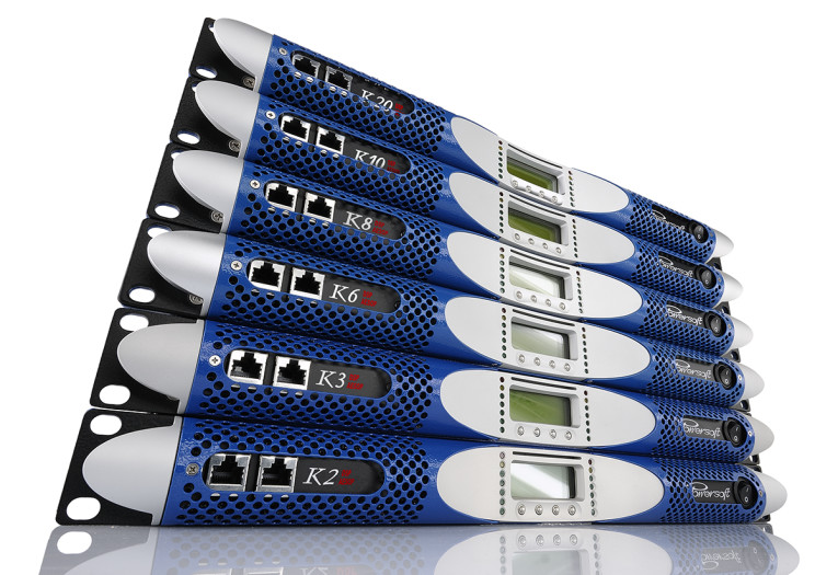
The second major section where efficiencies may be gained is the power supply (see Photo 3). Switch-mode supplies have revolutionized most consumer electronics goods in recent years. The high frequencies used obviate the need for a bulky, heavy power transformer capable of handling 50 or 60 Hz, so supplies can have a much lower weight.
Powersoft Audio’s X and K Series amplifiers (as well as most other models in their line) implement fixed-frequency switch-mode technology for both the power supplies and the output stages. Each stage in a fixed-frequency (FF) switch-mode amplifier is driven and synchronized by a global fixed-frequency clock signal. This entails a more complex electronic design than common variable frequency (VF) systems where the switching frequency of each stage is independent from one another, but it can reduce electromagnetic interference (EMI) emission (one of the challenges of switching supplies and amplifiers) and optimize matching between the power supply and the output stage current demands.
From the point of view of the dynamic response and SNR, FF switch-mode amplifiers have a more predictable and stable behavior. Performance is consistent over time and signal characteristics. For example, in a VF system, the leakage noise varies with the frequency. It rises when the switching frequency decreases (amplitude of the signal increases).
In a FF switch-mode amplifier the leakage noise is low and constant. The use of an FF also enables the cross-coupled notch filter trick mentioned earlier to remove switching noise from the output, which would be difficult or impossible to implement in a VF system. As a bonus, an FF system can show less EMI coupling among the output stages yielding fewer beat frequencies from amplitude modulation, very low intermodulation distortion (IMD), and reduced crosstalk among the channels.
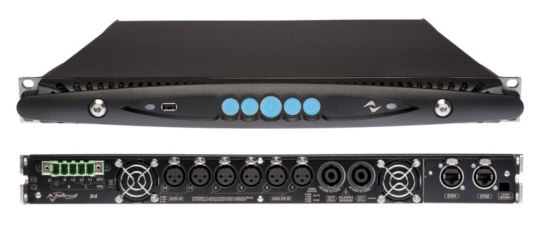
The fixed frequencies used in the Powersoft Audio amplifiers are multiples of 48 kHz for the switching frequency: This choice is consistent with the digital standard of working with multiples of 48 kHz for sampling frequency and helps make the interaction between DSPs and the amplifiers noise-free (see Photo 4).
Getting in Tune: Power Factor
Powersoft Audio claims to be the first to implement power factor correction (PFC) in pro amplifier power supplies (see the “Power Factor” sidebar for an overview). The use of PFC technology can achieve better efficiency, lower noise injected back into power lines, and lower distortion and noise. Because of the nonlinear nature of the amplifier’s load on the power line, the PFC must be an active circuit. Figure 1 and Figure 2 show oscilloscope plots for the primary voltages, currents, and powers of two amplifiers, respectively one with no PFC and one using PFC. Each amplifier is delivering a total of 4 kW (two channels at 2 kW per channel). The power line voltage waveform and value are shown in yellow. The current waveform and value are shown in cyan. And, the power drawn from the power line’s waveform and value are shown in red.
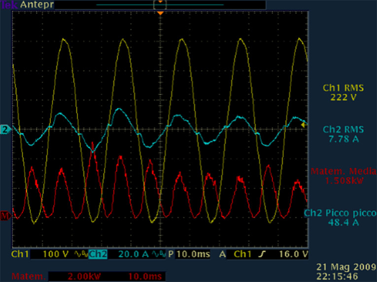
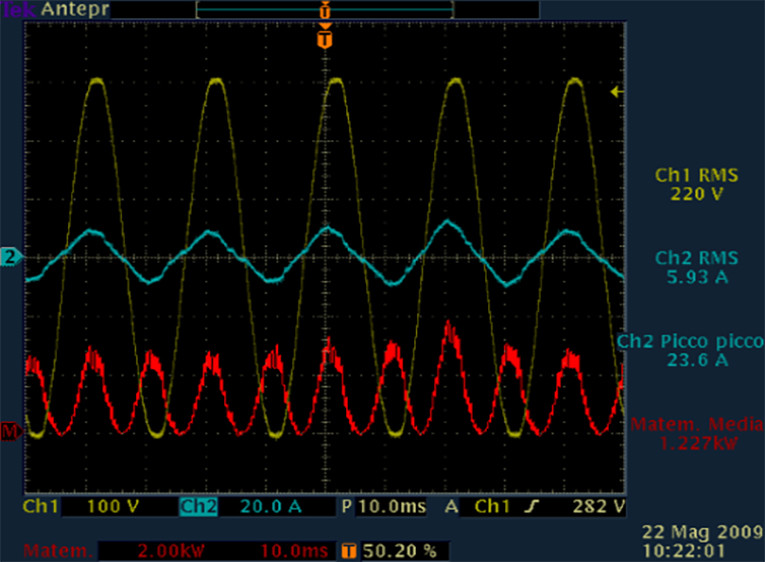
The non-PFC amplifier’s current waveform is less smooth compared to the corresponding waveform for the amplifier with PFC, implying high harmonic distortion components injected back into the power line. Although the current’s RMS value is about the same between the two solutions, Powersoft Audio’s PFC technology results in lower peak current value, reducing wiring losses and radiated EMI. Most importantly, the efficiency gains are dramatic. For the same output, the non-PFC amplifier draws 7.78 A RMS from the power line, whereas the PFC amplifier draws 5.93 A RMS.
Signal-Tracking Power Supplies
In any amplifier output stage, the efficiency is a function of the difference in the output voltage delivered to the load and the rails voltage delivered from the power supply. This is true for any amplifier, whether Class A, B, C, D, H, G, or letters yet to come, regardless of the differing efficiencies among these classes of operation.
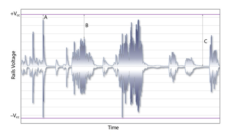
The Powersoft Audio’s Smart Rails Management (SRM) technology implements real-time voltage tracking in the power supply to minimize the differences between the output voltage and the power supply rail voltage to improve the overall efficiency. Figure 3 shows a graph of a musical signal waveform in a conventional amplifier, with the power supply rail voltages superimposed on the graph. At times of signal peaks (point A), the difference between the signal and the power supply voltage is small, so the wasted power in the output stage is low. As the signal reduces in amplitude (point B), the voltage difference increases, and wasted power, proportional to the square of the difference, increases even faster. Near idle (point C), nearly all the power dissipated in the output stage is wasted.
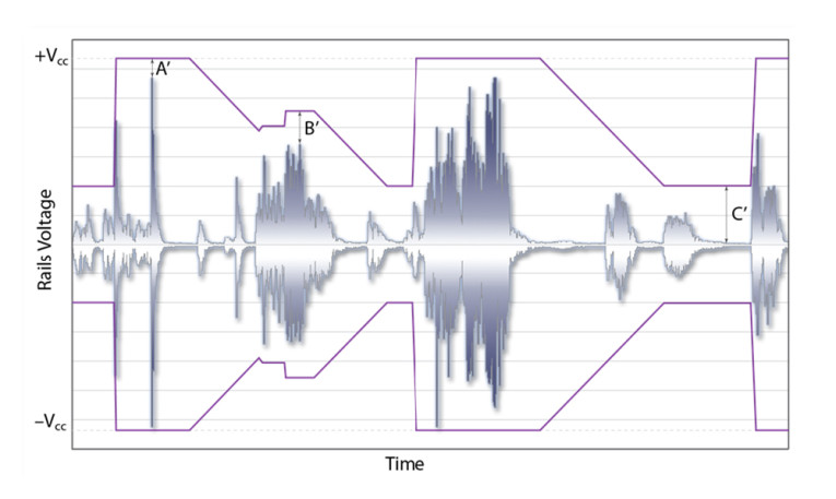
The SRM system attacks this issue by varying the power supply rails in synchrony with the signal (see Figure 4). It’s easy to see that at points B and C, the voltage difference between the power supply and the signal. Hence, the power dissipation in the output stage is significantly reduced. This is especially true at idle. For example, if an output stage dissipates 12.5 W at idle at full nominal rails (e.g., at ±150 VDC power supply), by halving the voltage (±75 VDC), the idle dissipation will reduce to 3.125 W, a net saving of 9.375 W per channel.
Contemporary power devices tend to have more switching losses than conduction losses, thus the efficiency driven by the amount of energy has to be switched to achieve a certain output voltage and current. With a reduced difference between the power supply voltage and the output voltage, switching losses are also reduced. As a bonus, reduction of the power supply voltage for lower amplitude signals provides a disproportionately high reduction in radiated radio frequency (RF) noise.
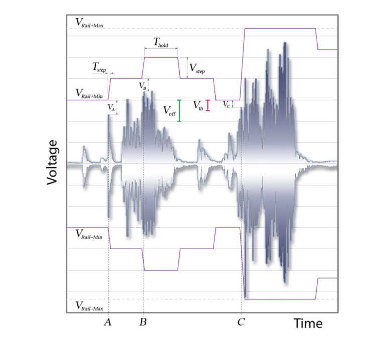
The SRM works by using a threshold detection system with the power supply rail voltage being incremented in steps VSTEP (see Figure 5). The power supply voltage, VRAIL is always greater than the output voltage VOUT. VOFF represents the offset voltage, VTH is the threshold voltage, and VA is the difference between the output voltage and the power supply rail value at point A (VC is the corresponding voltage for point C). At point A, VTH < VA < VOFF, so the power supply increments up VRAIL = VRAILMIN + VSTEP. At point C, VC < VTH so the power supply rail increments to VRAIL = VRAILMAX. The hold time THOLD accounts for dynamic VOUT modulation. For sake of clarity the picture has been simplified (i.e., real rising TSTEP is shorter than falling TSTEP).
Networking and Control
The other component of 21st century sensibilities is networking and control. The equalizers and crossovers that once took up several rack spaces and had lots of unreliable controls have been superseded by DSP implementations in software.
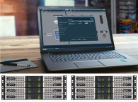
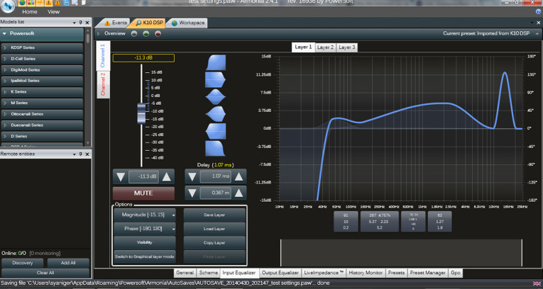
Powersoft Audio’s networking and control software system is called “Armonia.” Within the Armonia platform one can assign amplifier channels in multiamp setups, set crossover points and slopes, set delays, and perform some remarkably flexible EQ adjustments.
I was particularly impressed with how intuitive and easy it is to use this software. Without having to read any of the manuals or tutorials, I was able to get channels set up and assigned, and achieve whatever response curves I wanted with the crossover and parametric EQ settings. Photo 5 is a screenshot of one of the control pages, with the others accessible through the tabs. EQ and crossover filter shapes can be drag and dropped onto the response curve, then modified graphically by moving “handles”on the curves or by direct data entry in numerical windows. If you have less of a sense of adventure than I did, there are YouTube tutorials demonstrating the software functions.
DampingControl and LiveImpedance measurement are innovative technologies implemented in the X and K Series amplifiers. The active DampingControl technology adds a “virtual” negative and adjustable resistance in series with the output of the amplifier. This negative resistance is varied by sensing the actual load impedance, with a feedback loop controlling the amount of current (negative resistance) needed to compensate for the change in damping. It is recommended for low frequency (under 400Hz) use only. These functions are also controlled with Armonia by using the LiveImpedance tab to bring up the control window.
Because of Powersoft Audio’s use of Analog Device’s SigmaDSP platform, additional DSP functions are programmable through ADI’s SigmaStudio software (see Resources). For example, dynamic range adjustment, sample rate conversion, single or multiband compression, and advanced filtering options are directly available; there are also third-party algorithms that can provide even more signal processing capability with this DSP.
The Powersoft Audio amplifiers are optionally networked using KAESOP (AES Ethernet Simple Open Protocol), an Ethernet solution that is also capable of carrying the audio data in AES3 format. This enables easy networking through assignment of addresses for various components, and a redundancy with analog data transmission. Control of the network is also accomplished using Armonia (see Photo 6).
In an impressive demonstration, Powersoft Audio played music through an amplifier using the Ethernet communication with the analog input set up as a backup. While music played, the Ethernet cable was unplugged, and the sound didn’t miss a beat. When plugged back in, the system reverted to AES3 mode seemingly instantly.
The X Series amplifiers also have Audinate’s Dante as a native protocol. Dante takes networking to true plug and play, making data and control simpler and more easily addressable using wireless and portable computers and pads. No more walkie-talkies! And no more manually configuring networks.
All’s Well that Ends Well
The contemporary demands for high efficiency and network readiness are well-met in the Powersoft Audio amplifier line. Compared with what was cutting edge even just a few years ago, the capabilities of these amplifiers are remarkable. It’s hardly apropos to even call these “amplifiers” anymore; the category seems to have been transcended by the broad functionality. These sorts of products are best thought of as an electronic Swiss army knife, with any imaginable function available at the flick of a finger.
At the same time, the state-of-the-art energy efficiency and reduced carbon footprint for high power amplification has easily reached the point of diminishing returns. This is a great benefit for ecology and economy. If only I’d had this 40 years ago. aX
This article was originally published in audioXpress, August 2014.
Power Factor
It’s necessary to understand what power is to intelligently manage the conflicting goals of high power and efficient operation. In basic physics, power is defined as the rate at which energy (E) is consumed, or more formally:

or infinitesimally:

For systems with constant energy flow, this simplifies to E/t for any given time interval of length t. In basic electricity, we learn that power can be calculated by Ohm’s law, that is, P = IV.
This makes sense because energy is voltage times charge, and current is the time rate of change of charge. The derived unit of volts times amperes is watts. For a resistive load R, we can
equivalently write power as I2R or:

where R is the load resistance.
So why do engineers distinguish watts (power) from volt-amps (also power)? AC analysis provides a clue. For AC, both voltage and current are a function of time. Loads may be resistive, reactive, or a combination. Algebraically, the impedance Z is a complex sum of the resistance (R) and the reactance (X), Z = R + jX, where j is the imaginary operator (square root of –1), representing a 90° phase shift of the reactive component X with respect to the real component R.
For example, if we have a load of resistance R driven by an AC
sine wave of circular frequency and peak voltage V:

The average power is calculated by substituting the RMS voltage for V. Since for a sine wave, RMS voltage is (1/2) times the peak voltage, then average power is:

From a simple Ohm’s law consideration and the purely real nature of R, you can see that the current and voltage are in phase, and the power is at all times positive (i.e., all of the applied power is dissipated in the load R).
Now, put a reactive component like a capacitor C in series with R:

Because the real and imaginary impedances are out of phase by 90°, the power is sometimes positive and sometimes negative (i.e., some of the power in not taken up by the load, but is reflected back and absorbed by the generator or power line). As the real part (resistance) gets large compared to the imaginary part (capacitive reactance), the power wasted by flowing back to the source gets lower. Contrary, as the resistance gets small compared to the capacitive reactance, the power absorbed by the load decreases and wasted power increases.
Evidently, one would like the load to have no reactive component to maximize efficiency. The measure of efficiency here is called power factor (PF). PF is quantitatively defined by the cosine of the phase angle between current and voltage in the load. If they are in phase, then the power factor is 1. If they are 90° apart, the power factor is 0. Loads containing resistance and reactance will have a power factor somewhere between 1 > PF >0. Although capacitance was used in this example, the same considerations hold true for inductive loads and loads containing inductance, capacitance, and resistance. Passive PF compensation is often used on motors (resistors in series with inductors) to try to maximize PF and efficiency.
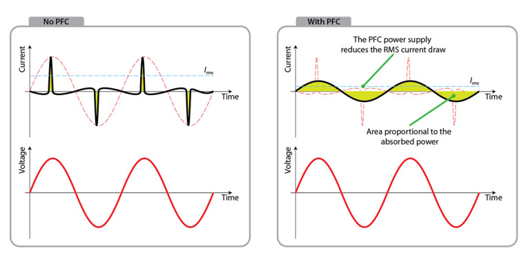
Nonlinear loads introduce a new complication: the distortion of the input current from a simple sine wave. Consider a typical full-wave bridge/capacitor filter power supply. Following turn-on, the capacitors charge up to the rail voltage. As the amplifier draws current from the capacitors, the voltage drops until it is below the pn junction drop of the rectifiers (typically 0.7 to 1.4 V, depending on topology). The rectifiers then switch on and charge the capacitor back up. Because of the capacitive load and the charging currents, the duty cycle of the current flow is much less than 1; the current waveform in the time domain looks like a series of spikes (see Figure 1).
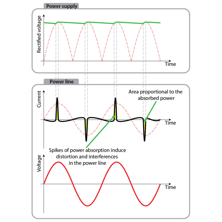
In the frequency domain, this is equivalent to the fundamental frequency and a long spray of high level harmonics (in this example, only odd harmonics because of the positive and negative symmetry of the current spikes). As a consequence, the peak current for this typical power supply load is considerably higher than the peak current of the same AC drive with a linear resistive load since nearly all the power to be delivered to the load must be transferred during the brief interval of the spikes.
What does this mean? Lower efficiency and higher losses - the power lost in the finite resistance of the power lines - is proportional to the square of the current, so a peak current of twice the peak current of a sine wave will cause four times the amount of loss in the line.
The lack of energy through most of the AC cycle means that the power factor is further reduced - one way to understand this is to consider the frequency spectrum of the pulses, which is equivalent to a sine wave with very heavy total harmonic distortion (THD). The reduction in power factor due to this distortion (DPF) is:
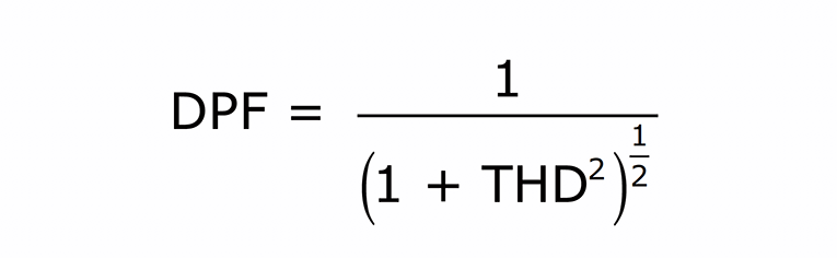
For the example waveform, THD is about 136%, so DPF = 59%. In other words, whatever the power factor was for a pure sine wave, it is now 41% lower. There is a steep efficiency penalty for current draws that are nonsinusoidal.
Being nonlinear, this PF loss cannot be corrected passively, but requires an active solution. Figure 2 shows the effects of proper power factor correction the RMS current draw (and hence power draw from the line) is significantly reduced by virtue of the “spreading out” of the current in the time domain. This is equivalent to a drastic reduction in the THD.
About the Author
Stuart Yaniger has been designing and building audio equipment for nearly half a century, and currently works as a technical director for a large industrial company. His professional research interests have spanned theoretical physics, electronics, chemistry, spectroscopy, aerospace, biology, and sensory science. One day, he will figure out what he would like to be when he grows up.
Resources
Audinate, www.audinate.com.
R. Erickson and D. Maksimovic, Fundamentals of Power Electronics, Springer, 2001.
C. Lastrucci, US Patent 6,281,767, “Reconstruction Filter for Eliminating the Switching Residue in Switched System,” www.google.com/patents/US6281767.
Powersoft Audio, www.powersoft-audio.com.
———, “Damping Control,” Technical Note #11 Rev. 01,
https://studylib.net/doc/18117657/damping-control---powersoft-audio