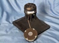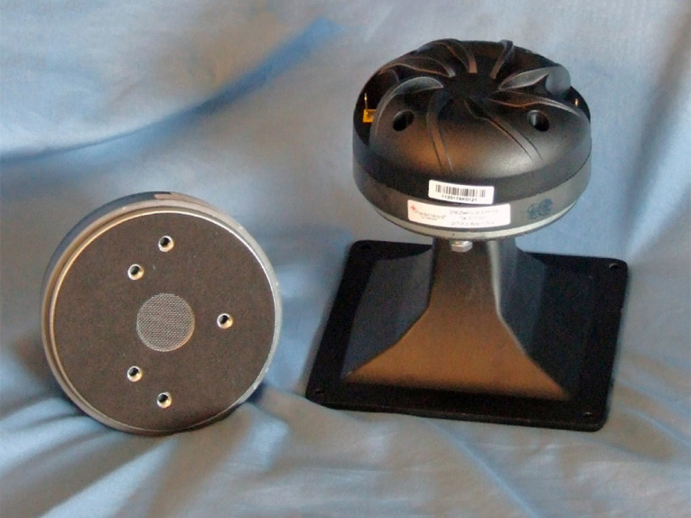

The DFM-2544R00-08 is driven by 44.4 mm diameter voice coil wound with aluminum wire on a Til film non-conducting former. Other features include a ferrite ring magnet motor structure, nominal 60 W rated power handling (50 W continuous), an injection-molded black heatsink, and solderable terminals. I should also note that the titanium diaphragm is coated with a light, thin layer of unique damping material giving the driver, according to the company, an unusually smooth sound at high SPLs. All of the materials resist environmental factors of heat, vibration, and aging and is purported to ensure many years of stable performance.
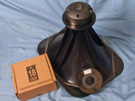
Since Tymphany does not yet produce horns for compression drivers, I used the B&C Speakers ME20 90° × 60° cast-aluminum exponential flare horn. Recommended crossover frequency for the DFM-2544R00-08 is 1.5 kHz, same as the low-frequency cutoff for the B&C Speakers ME20 horn.
I began testing using the LinearX LMS analyzer to produce the 300-point stepped sine wave impedance plot shown in Figure 1. The solid black curve shows the DFM-2544R00-08 mounted on the ME20 horn and the dashed blue curve represents the compression driver without the horn. With a 6.25Ω DCR (Re), the minimum impedance of the DFM-2544R00-08/ME20 was 6.86Ω and at 4.99kHz.

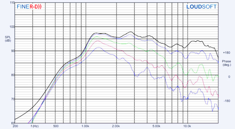


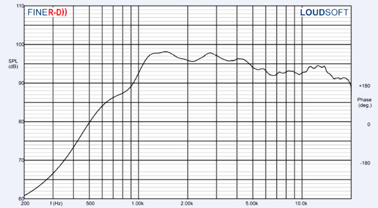
For the next set of SPL measurements, I free-air mounted the Peerless DFM-2544R00-08/ME20 without an enclosure and measured both the horizontal and vertical on- and off-axis at 2.83 V/1 m using a 100-point gated sine wave sweep from 0° on-axis to 60° off-axis. Figure 2 displays the on-axis frequency response of the compression driver/horn combination, which is smooth with no major anomalies with a declining response as frequency increases above 5 kHz, and extending to about 16 kHz.
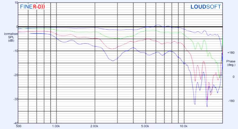
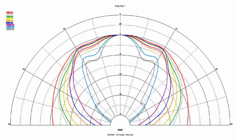
Figure 3 shows the on- and off-axis response in the horizontal plane. Figure 4 displays the normalized horizontal plane response. Figure 5 shows the CLIO Pocket analyzer’s 180° horizontal polar plot (in 10° increments with 1/3 octave smoothing applied). Figure 6 gives the on- and off-axis to 60° response in the vertical plane.
Figure 7 depicts the normalized vertical plane response. Figure 8 shows the CLIO Pocket generated vertical plane polar plot (in 10° increments with 1/3 octave smoothing applied). Last, Figure 9 illustrates the two-sample SPL comparison showing the two DFM-2544R00-08/ME20 compression driver samples to be closely matched within less than 1 dB throughout the transducer’s operating range.

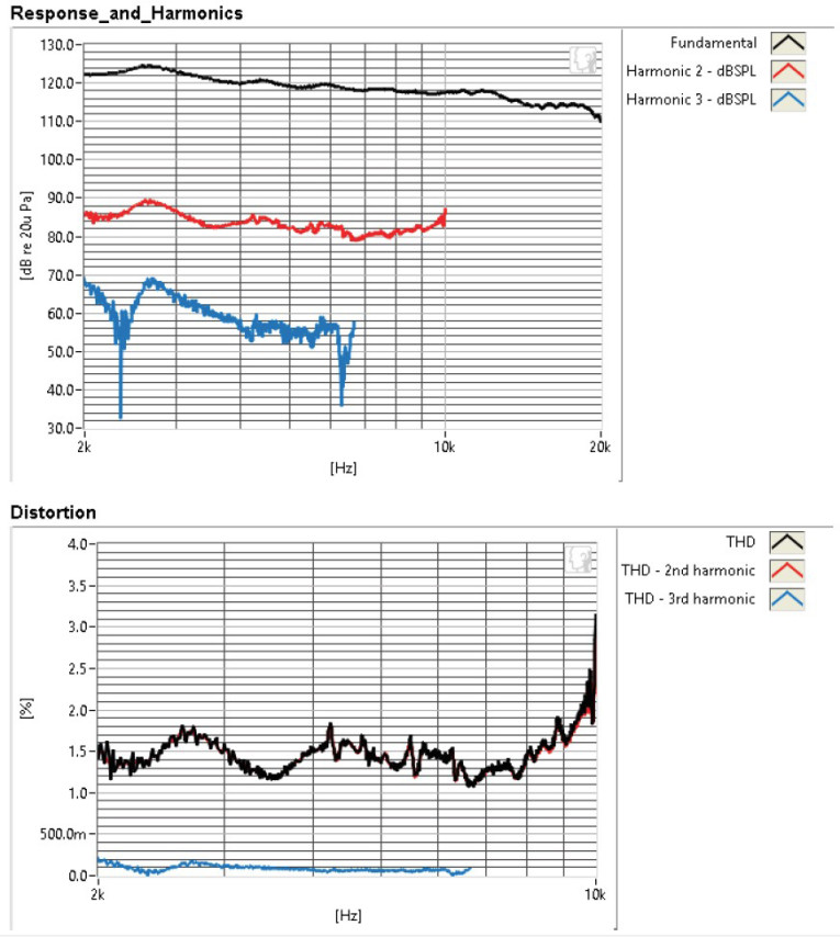

For the remaining series of tests, I again set up the Listen AmpConnect ISC analyzer and 0.25” SCM microphone to measure distortion and generate time-frequency plots. For the distortion measurement, I again mounted the DFM-2544R00-08/ME20 combination in free-air, in the same manner as was used for the frequency response measurements, and set the SPL to 104 dB at 1 m (3.05 V determined by using a pink noise stimulus generator and internal SLM in the SoundCheck 15 software).
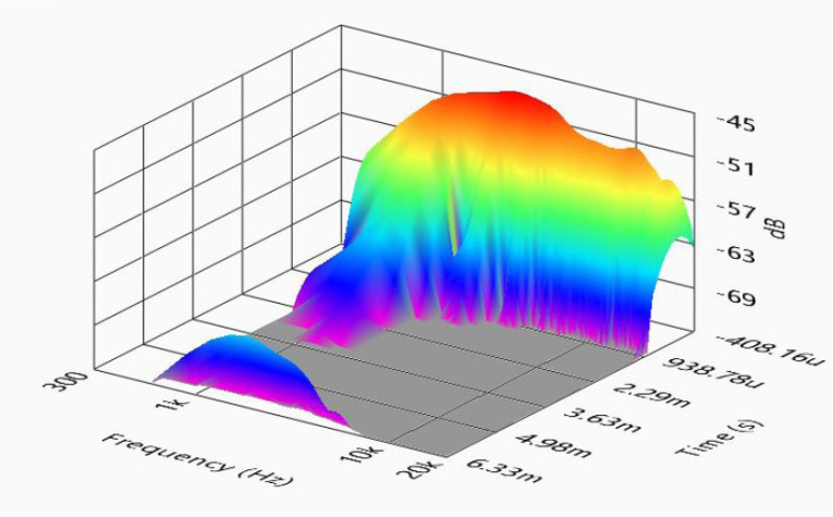
Then, I measured the distortion with the Listen microphone placed 10 cm from the mouth of the horn. This produced the distortion curves shown in Figure 10. Following this test sequence, I then set up SoundCheck 15 to generate a 2.83 V/1 m impulse response curve for this driver/horn combination and imported the data into Listen’s SoundMap Time/Frequency software. Figure 11 shows the resulting CSD waterfall plot. Figure 12 shows the STFT plot.
Tymphany is definitely one of the larger OEMs in the loudspeaker industry. The new DFM-2544R00-08’s performance is quite good and the build quality likewise excellent for a driver in its price category. For more information visit, www.tymphany.com/pro. VC
This article was originally published in Voice Coil, March 2018.