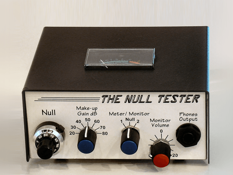
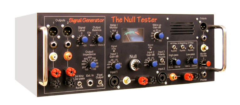
Over the years I’ve designed many audio devices including equalizers and crossovers, a distortion analyzer and other test equipment, a stereo synthesizer, and made modifications to pro audio devices, and much more. Many were published as DIY articles in a now-defunct magazine for recording professionals, and those that are still relevant are archived on my website (see Resources). But I still like to tinker, and my latest project is the Null Tester, shown in Photo 1 and Photo 2.
This device compares any two audio wires (plus some electronic components and other simple devices) to identify their differences. Audio quality is usually assessed by measuring the four standard parameters of frequency response, noise (including hum), distortion, and time-based errors (wow, flutter, and jitter). But some people wrongly believe there may be other properties missed in these standard tests.
How the Null Tester Works
The Null Tester avoids that potential objection by sending the same audio signal through two paths, then it electronically subtracts one signal from the other to obtain the difference. If the signals at the other end of the wires are identical, the result is silence. In other words: A – A = 0. Otherwise, the remaining residual can be assessed for audibility based on its volume level and content. Note that a null test doesn’t actually “measure” anything — yet it reveals all differences between two signals, including things for which you might not even be looking. One important use for the Null Tester is to compare a $3 RCA wire to a $1,000 RCA wire!
Irrational beliefs about “wires” are common among audiophiles, and even some famous recording professionals have claimed that spending thousands of dollars on signal wires is a worthy investment that yields an audible improvement. Such beliefs are often held by the same people who reject conventional measuring. I think there’s great value in devising a way to prove that two wires really do identically pass audio, and thus, by definition must sound the same no matter what someone believes they hear. This is what the Null Tester does, and in a way that cannot be refuted.
When comparing wires, the null residual will be 60 dB or more below the input signals, depending on the wire capacitance and other factors. So the Null Tester raises the gain after nulling in 10 dB steps between 20 and 80 dB, and the output amplifier can increase that to a maximum total of 114 dB. This lets you view even smaller residuals on an external voltmeter or oscilloscope. The balance required to obtain a null down to complete silence is so critical that tiny 2 pF to 6 pF variable capacitors are needed to ensure precisely equal phase shift in both signal paths. A phase difference as small as 0.006° is enough to limit the null depth to less than –80 dB, which is at the edge of audibility with certain types of program material under the most favorable conditions.
The Device
This device might become a commercial product, and there isn’t room to show the entire schematic anyway, but Figure 1 presents the most important parts. The input circuit isn’t shown, but Input 1 is a simple unity gain buffer and Input 2 is unity gain inverting, so the signals cancel near the middle of the 10-turn precision Null Control. Both input stages are DC coupled to avoid adding distortion from coupling capacitors. The first capacitor in the audio path is C7, and that’s a high-quality film type, though a small amount of distortion after the null pot wouldn’t be a big problem anyway.
I used OPA1612 op-amps having 0.000015% distortion (yes, really) and with an input noise level of only 1.1 nV/√Hz to minimize the Null Tester’s own artifacts as much as possible. Nulling is so sensitive that even with a 200 Ω 10-turn pot — the lowest value I could easily obtain — tweaking the pot for a complete null was too coarse when combined with the 5.1 kΩ series resistors. Adding 22 Ω in parallel simulates having a much smaller value.
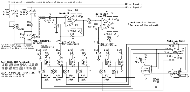
Figure 1 shows the digital gain-switching circuit I devised to avoid bringing the highly sensitive microvolt-level null residual off the board up to the rotary gain switch. The OR gates enable different combinations of gain spread across the two op-amp stages, with the second stage having a starting gain of 20 dB via R33. Transistor switches bring the gain resistors down to ground, and these particular transistors have an On resistance of only 35 mΩ. This greatly reduces the distortion that would occur when using normal transistors as gain switches with small signal levels, and allows using lower value gain resistors, which reduces circuit noise. These junction transistors also avoid the rising high-frequency response that could occur with field effect transistors (FETs), because the capacitance of typical FETs yields a relatively low impedance at high frequencies compared to the gain resistors.
Two-stage amplifiers like this usually put most of the gain in the first stage to minimize circuit noise, but that wasn’t practical here because the transistors would start to conduct when U4 Pin 2 gets much above one volt.
By putting the first 40 dB of gain in the second stage (U4), Pin 2 — which follows Pin 3 — is kept safely below one volt at all gain settings and signal levels. Having the first stage amplify the initial 20 dB to 40 dB would yield lower noise, but when the nulled residual is so large that only 40 dB or less total gain is needed, the circuit noise from a unity-gain first stage is moot. (I use the term “circuit noise” to describe the hiss sound you hear at high gain settings, but it’s more formally called thermal noise or Johnson noise after John B. Johnson who worked at Bell Labs in the 1920s.)
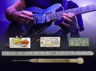
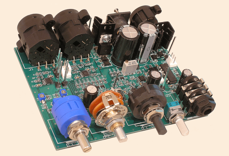
A four-layer PC board and surface-mount devices (SMD) reduce the board size and cost, though the 0805 SMD resistors I used are about 1/6 the size of a grain of rice! But soldering isn’t difficult with the right tools, 0.025” solder, and a lighted magnifier. In fact, learning to build a device using SMD parts made this project much more interesting and fun for me.
Further, many of the latest and greatest op-amps and other components are available only as SMDs. But be careful with SMD ceramic capacitors because their capacitance can reduce dramatically as the DC voltage across them rises. So you may need to buy parts that have a higher capacitance than required, based on the percentage reduction in the spec sheet under “DC Bias Characteristics” or similar wording. I have to admit that with my 70-year-old eyes I was a little fearful about trying to populate a PC board with such small components! But a good friend showed me how she does it, and it turned out to be surprisingly easy. The key is to first tin one pad with solder, then hold the part with tweezers and tack it onto the tinned pad. It might not be a perfect connection but that doesn’t matter. Then after you solder the other end of the component, you’ll come back and re-flow the first side.
I designed the unit and drew the schematic using the fabulous, free program from PC board maker ExpressPCB. A companion program to design circuit boards is also free, and accommodates boards with one, two, or four layers. One great feature of these sibling programs is they share common data, making it easy to confirm that the PC board layout matches your schematic. I designed the panel labeling in Microsoft Visio, then I printed it on card stock using 3M photo mount spray glue to hold it in place. I devised this method for my Mojo Maestro DIY article, which was published in the October 2017 issue of audioXpress, and it works well as long as you’re reasonably careful not to scratch it up.
Behind the Design
When I first thought to develop a Null Tester, I had grandiose plans to develop a serious product that could test and compare all sorts of audio devices. I used null testing in my Audio Engineering Society (AES) Audio Myths Workshop video to compare various software operations using WAV files. So it seemed only natural to develop an analog version to test audio hardware. For example, when you compare the input and output of an audio device, the null residual will contain only the noise and distortion added by the device. You can then measure the residual level relative to the output signal, and analyze its spectrum with a software Fast Fourier Transform (FFT), or even listen to assess its audibility.
One big feature of null testing is you can use music as a source signal. Many audio enthusiasts wrongly believe that sine waves aren’t good enough for testing audio gear. However, a very long time ago French mathematician Jean Baptiste Fourier (1768–1830) proved that music (and indeed all sound) is comprised entirely of sine waves. So by using music as a test signal, people suspicious of objective measuring with sine wave test tones lose an important argument!
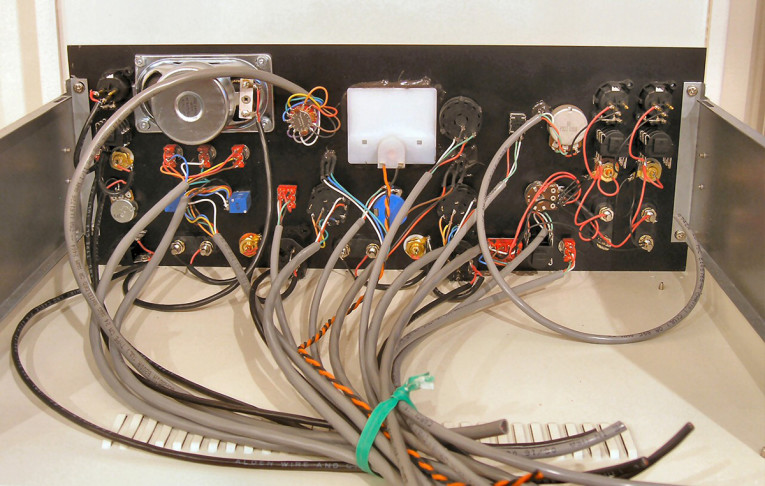
I spent $3,500 over two years designing and building the Null Tester shown in Photo 3 and Photo 4. I thought initially it would be a commercial product that could compete with $10,000 analyzers but sell for half the cost. So I designed a full-featured version containing a built-in multi-tone signal generator, 24 dB/octave sweepable high- and lowpass filters to exclude the frequency extremes when needed, A-Weighting, input padding to accommodate power amps up to 5,000 W, and much more.
Alas, once the unit was completed I realized that even a teensy amount of phase shift precludes getting a usefully deep null. That means it wouldn’t be feasible to compare preamps, or power amps, or most other common audio devices, unless complex variable phase compensation was also added. D’oh! I should have built and tested a simple breadboard version first. Fortunately, I knew that an analog null test could compare signal wires, even if nothing else, and that alone was worth doing. So I reduced the concept to that much simpler goal, and it was a success.
The Completed Tester
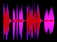
Once the reduced Null Tester was completed, I made a video to demonstrate the device in operation. The first part of the video explains all about null testing in detail, then the demonstration portion compares three inexpensive wires plus a $700 “boutique” wire. I don’t mind giving away the ending: All four wires were proven to pass audio identically down to a level below –110 dB. In fact, I didn’t think to make this important point in the video: The Null Tester’s inherent noise floor is –110 dB, but our ears can discern the presence of music and speech as soft as 20 dB below the noise. When the Null Tester is set for the deepest null, no music can be heard at all. That means the null is actually 130 dB down, or even more, not “merely” 110 dB. I wish I had thought to make that point where I show music being nulled out completely in the video!
Even though my grand plan to start a company selling this unique audio testing method didn’t pan out, I still consider the project a success. Clearly, the tests in my video prove there are no mysterious properties of audio that engineers don’t know about. They also show that human hearing perception is not as reliable as many believe, which is at least as important a point to make. Indeed, if two wires can be nulled to silence, that proves beyond all doubt they pass audio identically, no matter what you think you heard. aX
This article was originally published in audioXpress, June 2019.
 About the Author
Ethan Winer has been an audio engineer and professional musician for more than 45 years. His Cello Rondo music video has received nearly 2 million views on YouTube and other web sites, and his book The Audio Expert published by Focal Press, now in its second edition, is available at amazon.com and Ethan’s own web site ethanwiner.com. Ethan is also a principal at RealTraps, which is a US manufacturer of high-quality acoustic treatment.
Resources
E. Winer, “Ethan’s Magazine Articles (and Videos),” http://ethanwiner.com/articles.html.
E. Winer,“Audiophoolery,” http://ethanwiner.com/audiophoolery.html
E. Winer, “Build the Mojo Maestro,” audioXpress, October 2017,
www.audioxpress.com/article/you-can-diy-build-the-mojo-maestro
E. Winer, “Audio Myths Workshop,” presented at the Audio Engineering Society
(AES) Convention, October 2009.
www.youtube.com/watch?v=BYTlN6wjcvQ
E. Winer, “The Null Tester,” YouTube,
www.youtube.com/watch?v=ZyWt3kANA3Q
ExpressPCB, http://expresspcb.com